All Activity
- Last week
-

Connection Of Truss To Supporting Beam Column
Hafsa Azmat replied to Hasan Tariq's topic in Steel Design
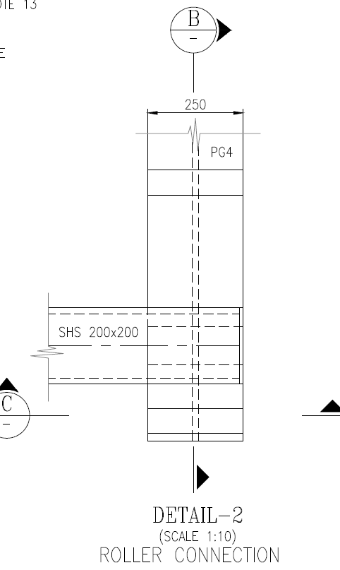
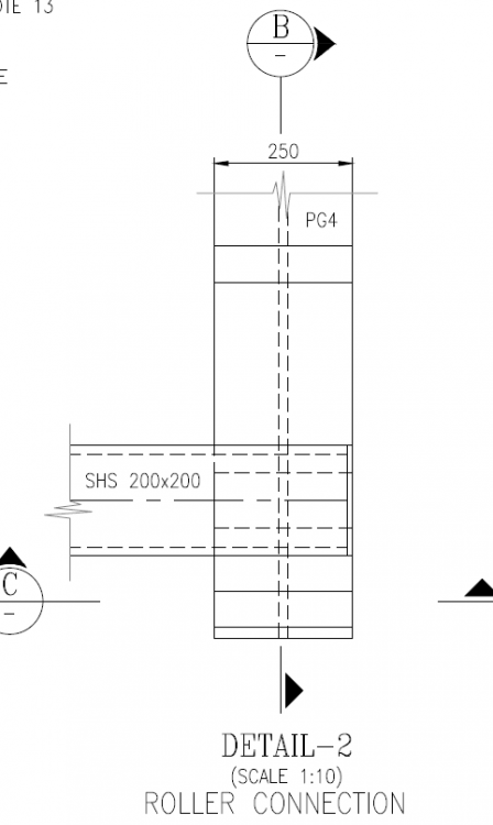
Hi, I have a similar scenario where the truss is subjected to both wind and temperature loading. I have assigned a hinge and roller support to the truss; the roller is translating in both directions because of wind and temp loading. To accommodate movement, I am using a ball bearing with stopper plates to restrict excessive displacement while providing the necessary deflection allowance. My Questions: 1. If the ball bearing comes into contact with the stopper plate at its extreme deflection limit, will the connection start behaving like a hinge? If so, do I need to check my truss supporting beam for additional reactions due to hinge behavior? 2. Would using a Teflon bearing plate solve this issue, or would it also behave like a hinge once it reaches its displacement limit? ( I donot know teflon plate behaviour) For example, if the truss deflection exceeds the allowable displacement range of the Teflon plate, will it introduce unintended forces at the connection? just like roller and stopper plate connection Would appreciate insight, Thank you Please advice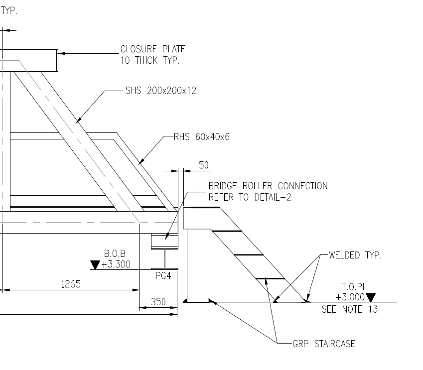

- Earlier
-
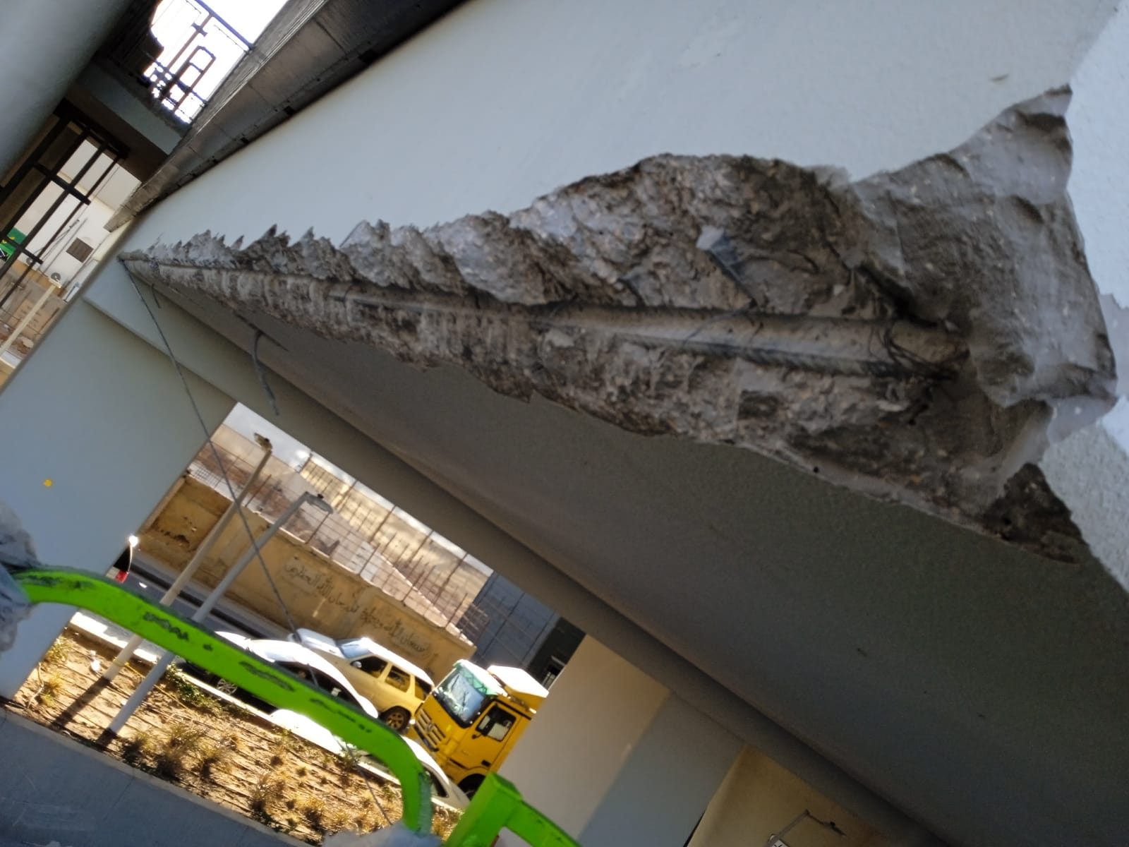
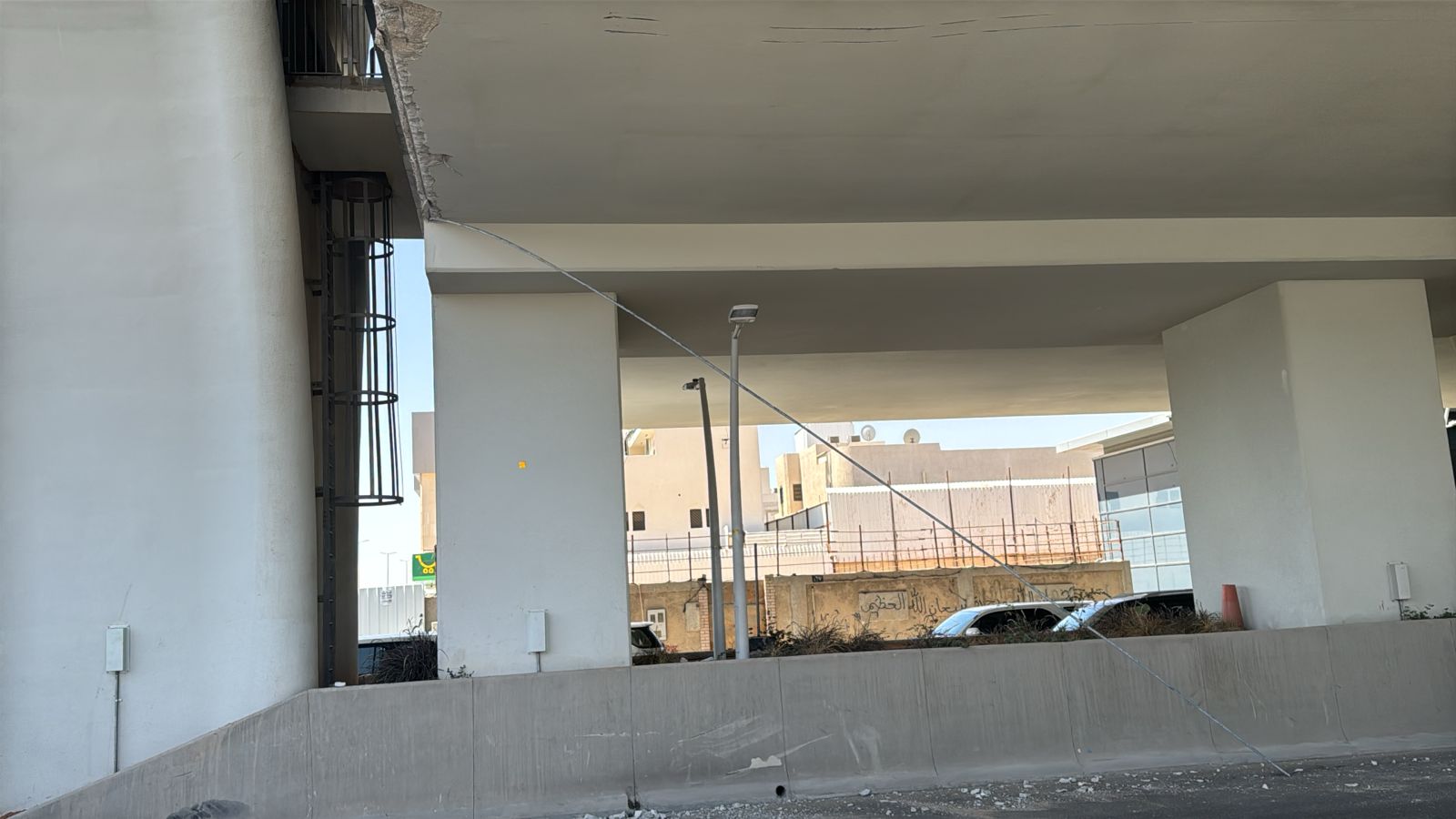
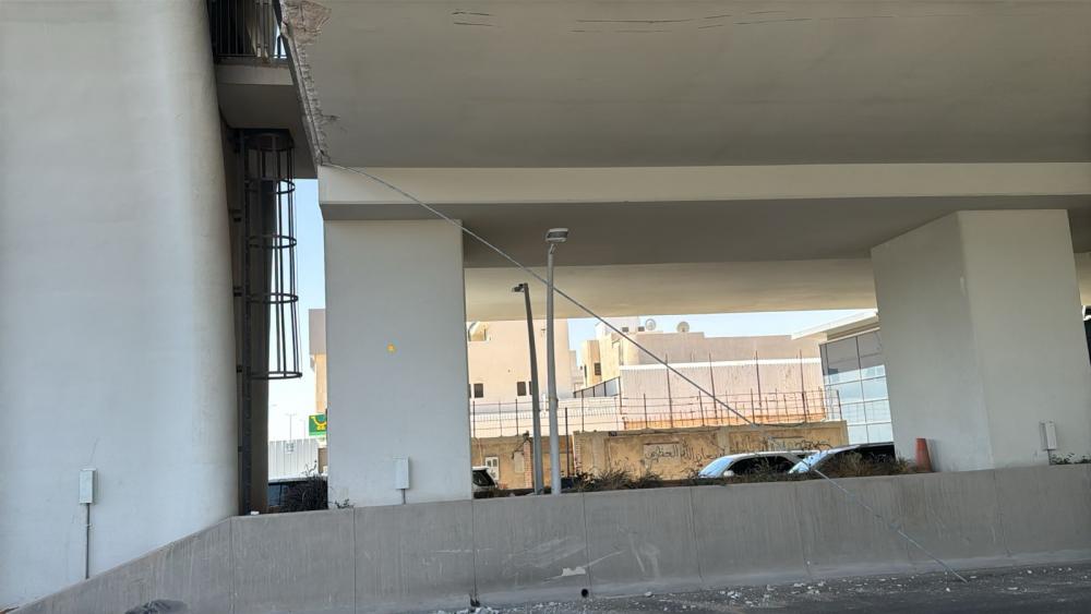
 Hi, Greetings sagacious colleagues, As per the attached pictures, could anybody assist me regarding the following concerns, Why is NDT required, if not why? Method of repair and what will be the plan on the damaged reinforcement, especially the main bar, will it be cut and use a new one through spliced (welding, stirrups, etc.)? Which type of material is to be required? Thank you.
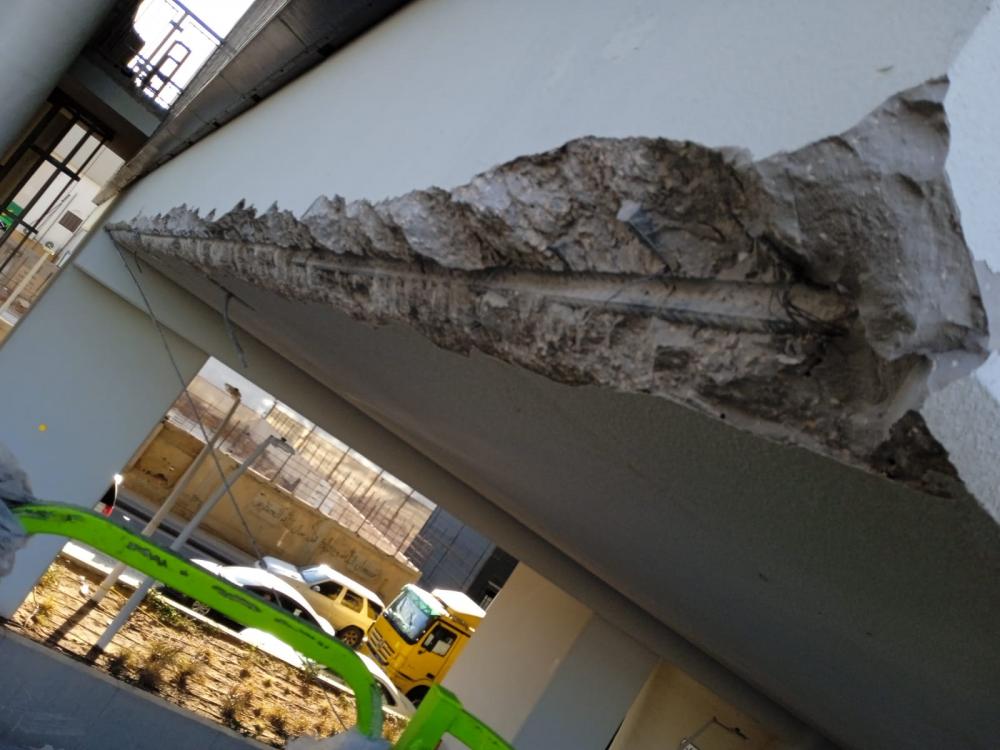
-
Strength design lateral loads
-
Should drift be checked in strength design condition or service condition of structure?
-

how to consider bouandary columns in shear wall
Tiger Hổ replied to BENTAFAT's topic in General Discussion
etabs solve this quite good. or you can use prokon to calculate shearW -
Cantilever beam failure no matter the size
Tiger Hổ replied to Alisha Pradhan's topic in General Discussion
Send the model included. 3m is too long for a normal cantiliver beam -
 Joint assignment for RCC Wall in basement in a frame structure modelled in SAP2000 Hello, I am designing a frame structure in SAP2000 which has a RCC wall in basement upto the bottom of floor beams. Should I divide the wall into 2'x2' squares and then assign fixed supports to all the wall shells or not?
 -
The cantilever beams fails in shear even if the size is increased. Can torsional modifier of 0.001 be applied on these beams considering the case of compatibility torsion? or is this the case of equilibrium torsion?
-
Dear Members, I am currently designing a warehouse with a span of 125'-0". The structure is being modeled as a metal building. Deflection is within allowable limits, but 6" deflection could disrupt roof components. Reducing the deflection further makes the metal building design uneconomical. To address this, I'm planning to design truss frame for comparison. Could you please recommend a suitable type of truss to resolve these issues? Additionally, any special guidelines for truss design would be greatly appreciated. Thank you in advance for your assistance.
-

Difference in result betwen FEM and strip in SAFE
FouziBel replied to Leomessi90's topic in Software Issues
Hi there, I had the same issue, and the FEM results in tables are per unit width (1 m), so Modeled the strips with 1 m width, and the results are way much different (almost 50% less than those on fem results table !! so what would be the problem? -
Did u find the proper way . what should be the modifiers for wall resisting soil load in one side of building. since its part of building what should be modifier used
-
 Asad Ullah Khan changed their profile photo
 -
 ADMIN PORTAL changed their profile photo
 -
 Muhammad Hashim changed their profile photo
 -
N/C stands for Not Calculated. It could be due presence of line load or any structural element like beam on that joint. There is the possibility that the joint didn't have any axial load assigned. You can check for these things hopefully you will get the required output.
-
 Muhammad Hashim reacted to a post in a topic:
Construction Of Special Moment Resisting Frame
Muhammad Hashim reacted to a post in a topic:
Construction Of Special Moment Resisting Frame
-
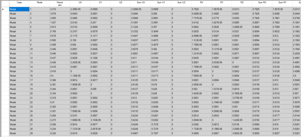
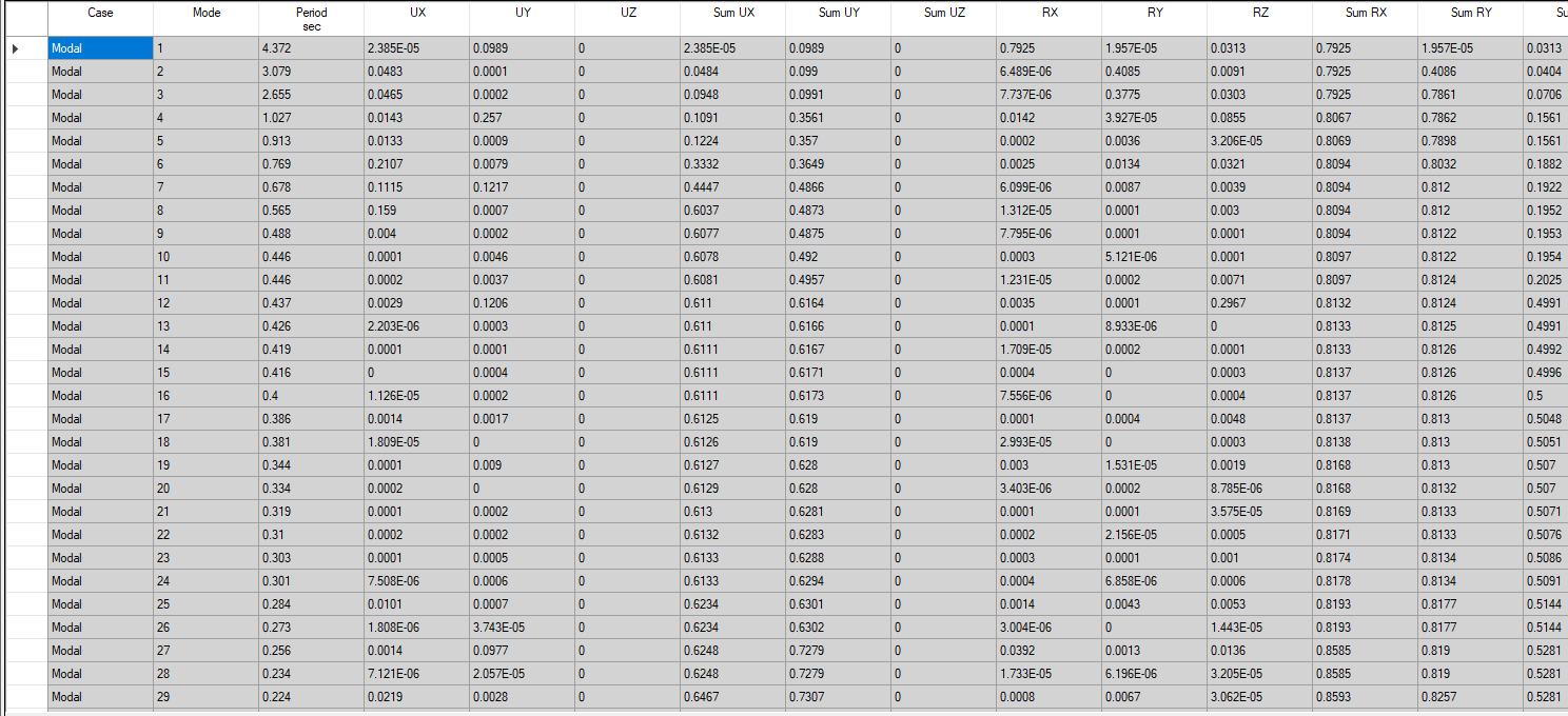
AoA Everyone, I need some guidance in modal Analysis. I am assigned to modal a structure in zone 2B region. After successful modelling, My first 30 modes is neither translation nor torsional. I have go through the model to find the error but it is all correct and according to the architecture plan. Can someone guide me. What should I do to make the first three modes as translation and torsional mode. My structure has 4 floors including 2 basements.
-
Engineering should focus more on practical experience and real-world applications, fostering a passion for innovation rather than merely preparing graduates for theoretical knowledge.
-

Strut-&-Tie Modelling in SAP2000
josem wily replied to Shahzad Khan's topic in Spreadsheets & Softwares
Sure! Here's a human-like reply for the forum: Has anyone come across a good video tutorial, PDF document, or any reliable source for learning the modeling of the strut and tie approach in SAP2000? I’ve been searching for some practical examples but haven’t found a clear guide yet. Any suggestions? Also, am I missing something important or making any common mistakes while using this method in SAP2000? Sometimes, it feels like I’m not getting the load distribution right. By the way, if anyone needs help with utility-related stuff, you can check out my website FESCO Bill for info about billing services! -
Waqar Saleem reacted to a post in a topic:
Do you or you company undertake structural design to Eurocodes?
-
 Hi all, Did u all encounter this kind of error before in etab? I tried to figure out and cannot solve it. If anyone hv solution kindly let me know . Thanks, Thinn
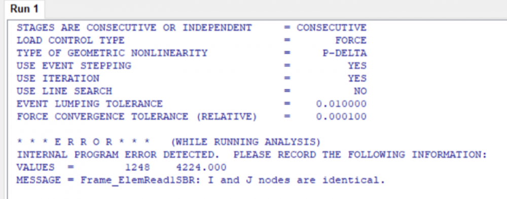
-
Waqar Saleem reacted to a post in a topic:
Need structural design engineering training.
-
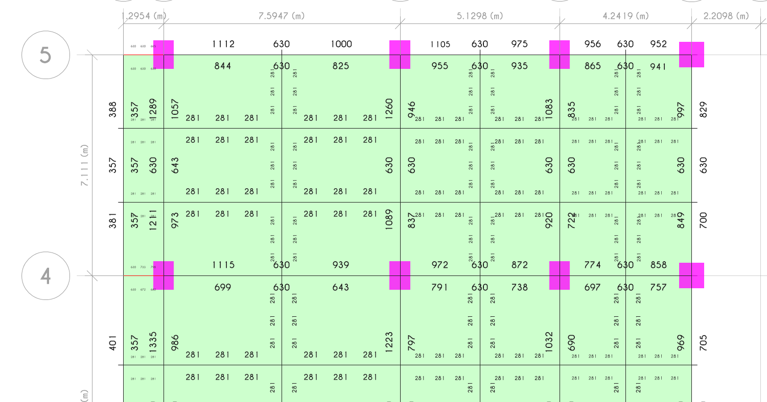
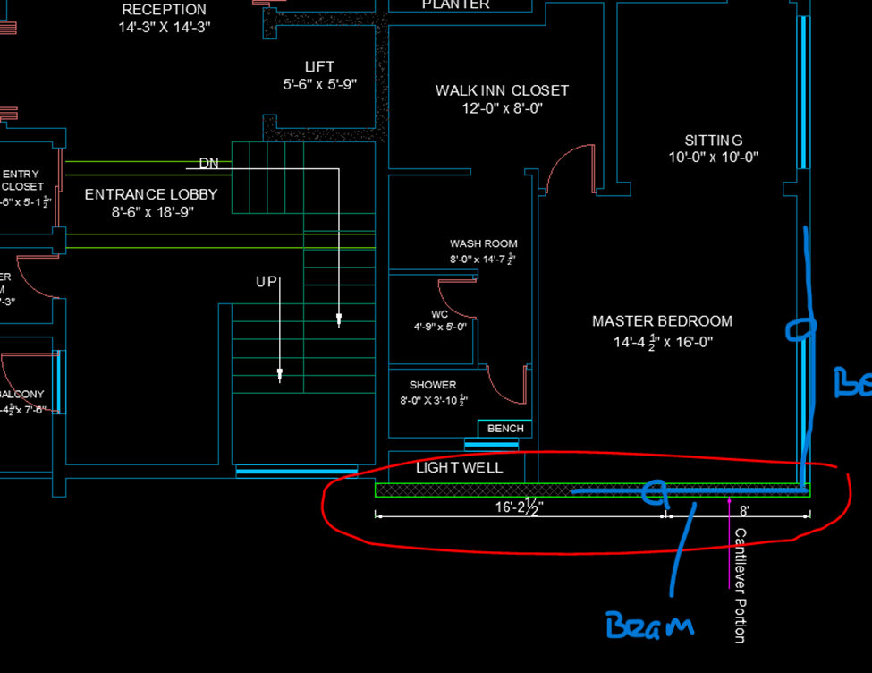
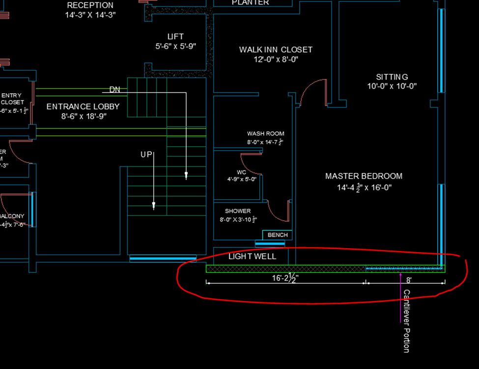
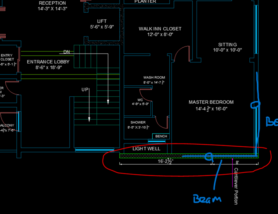
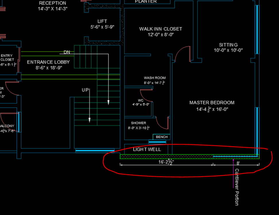
Hi, You can add two columns at ends of window where circles are marked and add beams, one beam could be cantilever and other can rest on it or both beams could be cantilever.
-
Hi, if RC column you go use maximum reinforcement or can use composite section with W section steel member.
-

Enhancing Knowledge Sharing: The Importance of Forums
Waqar Saleem replied to Hamza Irshad's topic in General Discussion
Yes Hamza, Discussion on forums is more productive and could be retrieved later for review or further improvement, Watsapp groups are also good but not that beneficial. -
Waqar Saleem reacted to a post in a topic:
Enhancing Knowledge Sharing: The Importance of Forums
-
interested to learn
-
For a composite structure i.e load bearing structure (Residential B+G+1ST) For the corner window, there is no vertical member i.e column, the beam is supported just on a 9” solid load-bearing wall at the lintel level i.e below the slab at the door level, is this arrangement of cantilever beams works??
-
Muhammad Faizan reacted to a post in a topic:
Guide for Response Spectrum Analysis
-
What can be done of the axial load of a column exceeds limit and the size of the column cannot be increased?
-
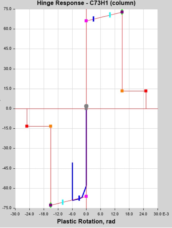
I hope you are doing well. I am performing NL dynamic analysis by using Sap2000. I am using a macro modeling approach for the infill walls. for the infill walls, I am using the link element approach and I am stuck on the point of "how to design force displacement curve in the link element ? I have read a couple of research papers and also saw some books but I am still finding difficulties regarding this hinges. if you have time can we have a little discussion on this?
-
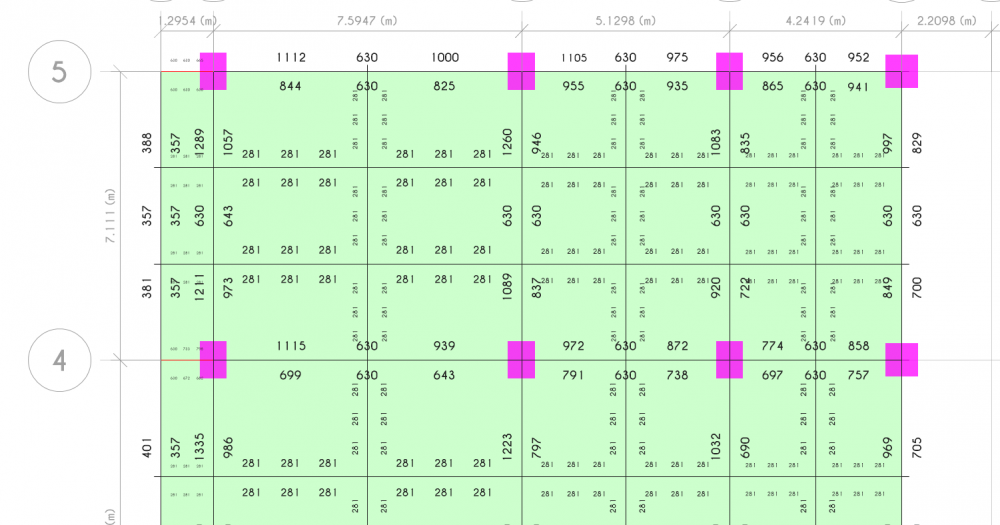
I'm having a hard time understanding this table. My supervisor said the sum of Ux Uy Uz Rx Ry Rz for the first three mode should be 100% but now it is not. Also for the first three mode there should be at least one cell from Rx Ry Rz to be a relatively large number respectively. Could anyone help me with that please!