Leaderboard

Popular Content
Showing content with the highest reputation on 03/09/15 in all areas
-

Torsion: Reinforced Concrete Members
Omer Ahmed reacted to UmarMakhzumi for a topic
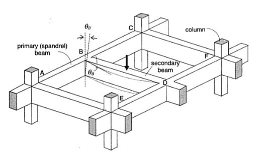
*SEFP Consistent Design* *Torsion: Reinforced Concrete Members * *Doc No: 10-00-CD-0001* *Date: May 24, 2013* Torsional forces, generally speaking, occur in combination with flexural and transverse shear forces. From a design perspective, we need to understand difference between two torsion types: Compatibility Torsion Equilibrium Torsion Compatibility Torsion Compatibility Torsion is when a member twists to maintain deformation compatibility; its induced in structural members by rotations (twists) applied at one or more points along the length of member. The twisting moments induced are directly dependent on the torsional stiffness of the member. These moments are generally statically indeterminate and their analysis necessarily involves (rotational) compatibility conditions(click on the image to enlarge). For the floor beam system shown above, the flexure of the secondary beam BD results in a rotation ǾB at the end B. As the primary (spandrel) beam ABC is monolithically connected with the secondary beam BD at the joint B, deformation compatibility at B implies an angle of twist, equal to ǾB at spandrel beam ABC, and a bending moment will develop at the end B of beam BD. The bending moment will be equal to, and will act in a direction opposite to the twisting moment, in order to satisfy static equilibrium. The magnitude of ǾB and the twisting/ bending moment at B depends on the torsional stiffness of the beam ABC and the flexural stiffness of beam BD. Now here is the fun part, the torsional stiffness of a reinforced concrete member is significantly reduced by torsional cracking. So, if you don’t design your spandrels for compatibility torsion, they will crack, increasing ǾB and reducing the induced twisting moment. To paint the same picture while using ETABS, set your torsional stiffness of the main beam to zero. This will also increase the amount of flexural reinforcement in your secondary beams. Moreover, considering design practice in Pakistan (since we never design beams without shear reinforcement), compatibility torsion can be ignored for regular structures, as minimum shear reinforcement in most cases would stand up to cracking torque. From ACI 318 commentary R11.6.1, Do note that there are some situations (such as circular beams supported on multiple columns) where both equilibrium torsion and compatibility torsion coexist. Also, eccentrically loaded beams, member curved in plan, and member of space frames will be subjected to torsion. See the attached “Timesaving-TorsionDesign-IA.pdf” as a go-by. Timesaving-TorsionDesign-IA.pdf Equilibrium Torsion In simplest words, Torsion is a limit state in this condition; a structure is subjected to equilibrium torsion when it can maintain equilibrium only by resisting the torsion. In such a case, torsional moment cannot be reduced by redistribution of internal forces since the torsional moment is required for the structure to be in equilibrium. From ACI- 318 (click on the image to enlarge). Moreover, see the structures below that defy gravity when subjected to different kind of loads by standing up to equilibrium torsion. Overall Building Torsion For overall building torsion, the torsional effects can be minimized by reducing the distance between the center of mass and center of rigidity. Center of Mass is the point where the mass of an entire story is assumed to be concentrated. The center of mass is crucial as the location of seismic force at a particular level depends upon it. The distance between the Center of Mass and the Center of Rigidity should be minimized, but may not be possible due to building geometry. Invariably, effects of torsion are present in at all buildings although analysis may show that in some buildings torsional effects are negligible.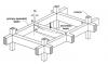
 1 point
 -
Assalam-o-alaikum! Narrating, what Umar has said, in another form and in some detail, my comments are as under: From structural point of view, the design information we require (from a manual calculation, or a structural software), is somewhat DIFFERENT in case of Structural Steel and reinforced concrete (RC) members. In case of structural steel frame design, we are interested in knowing the 'capacity ratio' (= maximum stress, caused by applicable load combinations / permissible stress) of a member, to decide whether the member has passed (indicated by 'capacity ratio' <= 1), or failed (capacity ratio > 1). On the other hand, for the RC frame members, we want to know whether a particular member has failed? (so that its size could be revised). And, if it is passed, what is the required reinforcement ratio / percentage? The failure or passing of a RC member is based on the reinforcement ratio (or percentage). For passing of a member, the reinforcement ratio (or percentage) MUST be within code prescribed limits. For the steel members, ETABS does provide values of capacity ratios DIRECTLY. However, in case of RC members it does so INDIRECTLY by provides required reinforcement quantities / percentages and warning / error messages, to indicate whether the member has passed or failed. A 'passed' member is indicated by 'required reinforcement being WITHIN code-prescribed limits' and 'NO error / warning messages'. On the other hand, a member will 'fail', if the required reinforcement is OUTSIDE code-prescribed limits, accompanied by error / warning messages, indicating structural deficiencies in relevant respects_shear, torsion etc). In case of RC Shell elements (slabs, walls etc) however, it is possible in ETABS to check various type of stresses. This can be done using following (ETABS version 9) menu command (for the defined load combinations): 'Display --> Show Member Forces/Stress diagram --> Shell Stresses/Forces' (Select Component Type 'Stresses') Regards.1 point
-

Torsion: Reinforced Concrete Members
UmarMakhzumi reacted to EngrUzair for a topic
This warning message appears in cases, where the calculated value of shear and torsion stresses, EXCEEDS the value permitted by the code. Generally, it requires increase in the member cross-section. Regards.1 point -
Torsion: Reinforced Concrete Members
Sami Ullah Khan Bangash reacted to EngrUzair for a topic
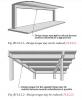
Thanks for a good informative article on torsional aspects of RC members. However, it is suggested that references to relevant codes or documents should be complete, for easy following of information and checking back the original reference for further study. For example, it took me a while to figure out which edition was being referred to, since the year of ACI 318 being referred was missing. Accordingly, a little addition of references. The above article refers generally to section 11.6 of 2005 edition of ACI 318 (ACI 318-05). In 2008 and 2011 editions (ACI 318-08 and ACI318-11), however the relevant information has been moved to section 11.5. The quote portion, in new codes, is in section R11.5.1, and the new figure numbers are Fig. R11.5.2.1 and R11.5.2.2 respectively.1 point -
interesting and most common... you have more reinforcement at upper columns because less axial force and more moment....so more eccentricity...more reinforcement while columns below have less moment and more axial force...as compared with the top columns meaning less eccentricity so less reinforcement from where more moment is coming on top columns? solve a portal frame 2 bay by 3 stories!1 point
-
Construction Of Special Moment Resisting Frame
Muhammad Hashim reacted to UmarMakhzumi for a topic
Its more than that. You have to see what seismic zone your building lies and have to select the appropriate level of ductility and over-strength. I would recommend skimming through ACI Chapter 21. I have also attached some documents pertinent to the discussion that will help you develop a better understanding of aforesaid. Go through read them and if you have any question post in the forums Goodluck! How do Beam-Column Joints in RC Buildings Resist Earthquakes.pdf How do Columns in RC Buildings Resist Earthquakes.pdf How to make building ductile for Good Seismic Performace.pdf How do Earthquake Affect Reinforced Concrete Buildings.pdf What is seismic design philosophy of Buildings.pdf1 point

This leaderboard is set to Edmonton/GMT-06:00