Leaderboard

Popular Content
Showing content with the highest reputation on 03/29/15 in all areas
-

Torsion: Reinforced Concrete Members
Omer Ahmed reacted to UmarMakhzumi for a topic
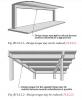
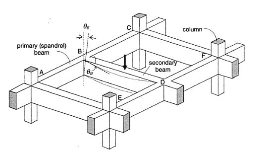
*SEFP Consistent Design* *Torsion: Reinforced Concrete Members * *Doc No: 10-00-CD-0001* *Date: May 24, 2013* Torsional forces, generally speaking, occur in combination with flexural and transverse shear forces. From a design perspective, we need to understand difference between two torsion types: Compatibility Torsion Equilibrium Torsion Compatibility Torsion Compatibility Torsion is when a member twists to maintain deformation compatibility; its induced in structural members by rotations (twists) applied at one or more points along the length of member. The twisting moments induced are directly dependent on the torsional stiffness of the member. These moments are generally statically indeterminate and their analysis necessarily involves (rotational) compatibility conditions(click on the image to enlarge). For the floor beam system shown above, the flexure of the secondary beam BD results in a rotation ǾB at the end B. As the primary (spandrel) beam ABC is monolithically connected with the secondary beam BD at the joint B, deformation compatibility at B implies an angle of twist, equal to ǾB at spandrel beam ABC, and a bending moment will develop at the end B of beam BD. The bending moment will be equal to, and will act in a direction opposite to the twisting moment, in order to satisfy static equilibrium. The magnitude of ǾB and the twisting/ bending moment at B depends on the torsional stiffness of the beam ABC and the flexural stiffness of beam BD. Now here is the fun part, the torsional stiffness of a reinforced concrete member is significantly reduced by torsional cracking. So, if you don’t design your spandrels for compatibility torsion, they will crack, increasing ǾB and reducing the induced twisting moment. To paint the same picture while using ETABS, set your torsional stiffness of the main beam to zero. This will also increase the amount of flexural reinforcement in your secondary beams. Moreover, considering design practice in Pakistan (since we never design beams without shear reinforcement), compatibility torsion can be ignored for regular structures, as minimum shear reinforcement in most cases would stand up to cracking torque. From ACI 318 commentary R11.6.1, Do note that there are some situations (such as circular beams supported on multiple columns) where both equilibrium torsion and compatibility torsion coexist. Also, eccentrically loaded beams, member curved in plan, and member of space frames will be subjected to torsion. See the attached “Timesaving-TorsionDesign-IA.pdf” as a go-by. Timesaving-TorsionDesign-IA.pdf Equilibrium Torsion In simplest words, Torsion is a limit state in this condition; a structure is subjected to equilibrium torsion when it can maintain equilibrium only by resisting the torsion. In such a case, torsional moment cannot be reduced by redistribution of internal forces since the torsional moment is required for the structure to be in equilibrium. From ACI- 318 (click on the image to enlarge). Moreover, see the structures below that defy gravity when subjected to different kind of loads by standing up to equilibrium torsion. Overall Building Torsion For overall building torsion, the torsional effects can be minimized by reducing the distance between the center of mass and center of rigidity. Center of Mass is the point where the mass of an entire story is assumed to be concentrated. The center of mass is crucial as the location of seismic force at a particular level depends upon it. The distance between the Center of Mass and the Center of Rigidity should be minimized, but may not be possible due to building geometry. Invariably, effects of torsion are present in at all buildings although analysis may show that in some buildings torsional effects are negligible.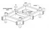
 1 point
 -

How Much An Average Etabs User Can Pay For Online Training Courses
WR1 reacted to EngrJunaid for a topic
Respected brother I think reasonable fee affordable for almost everyone should be; 1) Basic - General, overview of softwares, basic modelling, analysis and results = 8000 PKR 2) Advanced - Complex modelling, detailed design of different elements, detailed analysis techniques = 12000 PKR 3) Pro - Dynamic, lateral, serviceability analysis = 16000 PKR1 point -
WAA! 1. The difference between total height 'h' and effective depth 'd' of a reinforced concrete beam is certainly calculated based on certain rules, as per applicable design code. These rules are explained in following paragraphs. 2. This difference, say 'dt', in case of the beams with main reinforcement in single layer only, is given by the relation: dt = cc + dbs + dbm / 2 Where 'cc' is the clear cover outside the stirrup, 'dbs' is the diameter of stirrup bar, and 'dbm' is the diameter of main reinforcing bar For example, if cc = 1.5 in., dbs = 0.5 in. (#4 bar) & dbm = 1.0 in. (#8 bar), then dt = 1.5+0.5+(1.0)/2 = 2.5 in. 3. For beams, with main reinforcement in more than 1 layer, 'dt' may be calculated using following relation: dt = cc + dbs + distance to centroid of main reinforcement, above stirrup level Note: 'dt' may be taken as 3.5 and 4.5 in. respectively, for beams with main reinforcement in 2 and 3 layers, when the diameter of main reinforcing bar does not exceed 1.0 in. (#8). Regards.1 point
-
Assalam-o-alaikum! You may need to go through following steps, to reach the conclusion in this regard: 1. Calculate standard deviation of concrete strength data, as per ACI 214.4. a. If you want to learn, how the standard deviation is calculated, you may refer to the following link: https://www.easycalculation.com/statistics/learn-standard-deviation.php b. You may also use 'standard deviation calculator' available at following link, to calculate standard deviation: https://www.easycalculation.com/statistics/standard-deviation.php 2. To determine whether the lowest value is an outlier or not, calculate the the quantity, Q, given below: Q = (Average value of strength data - minimum value of strength data) / Standard deviation 3. From what I have understood from the study of ACI 214.4, ASTM E 178 and other sources I came across in this connection, you have to compare the value of Q calculated above, with the value given in Table 1 of ASTM E 178 at the 1.0% significance level for a set of six observations (since you have 6 strength test values). IMO if your calculated Q value is more than than the relevant value given in Table 1 of ASTM E178, your lowest value would be outlier. (I might be missing something here, as I have not dealt with this subject earlier. And, therefore would request others to correct me, in case I have faltered somewhere). 4. ASTM E 178 may be downloaded from the following link: http://library.sut.ac.th:8080/astm/cd14022005/PDF/E178.pdf HTH Regards.1 point
-

Design For Shear And Torsion Using Etabs
Omer Ahmed reacted to Syed Umair Haider for a topic
Dear Zain, I don't know the origin of document,you have uploaded for calculating torsional constant,but the methodology given therein is incorrect.As "Tcr" and "Tu" given therein are indeed threshold torsional strength and ultimate torsional stresses respectively, and are both design properties not analysis properties. (See ACI 318-11 section 11.5.1). Whereas the torsional constant, ETABS asks in "analysis property modification factors" is simply the torsional moment of inertia (J) used to determine torsional stiffness of a member (JG/L) i.e something else. As long as its value is concerned,then in building structures it is a general practice to use a negligible value like .001 to nullify beam's torsional stiffness.In this way, the torsional stresses (if arising due to compatibility of deformation i.e compatibility torsion ) are transferred via alternate load path (i.e redistribution of torsional moments occurred), considering that beam is unable to provide torsional restraint and in other condition if torsional stresses in beam is required to satisfy equilibrium of structure (where redistribution is not possible) then torsional stresses in beams remains independent of whatever value of "J" you have selected as equilibrium equations are necessarily satisfied independent of stiffness as "Compatibility is optional and equilibrium is essential". This approach of minimization of "J" economize beam sizes that arise from stringent combined shear and torsion requirement of building codes,but consequently beam sections designed in this way will start developing internal horizontal cracks (hairline cracks not affecting functionality of structure) due to torsional stresses and their torsional strength will continuously degrade till the design condition is achieved i.e negligible torsional strength of beam.But as the structure is designed to be stable without torsional stiffness of beam so it remain stable after this condition is achieved.However, the beam member itself cracks that doesn't affect the functionality of structure in any way. A very descriptive and clarifying description is available in "Reinforced concrete design by Arthur Nilson". As long as authentication of this approach is concerned then it is allowed by building codes as, 1, ACI-318-11 section 11.5.2.1 & 11.5.2.2. 2, UBC97 section 1911.6.2.1 & 1911.6.2.2 3, BS 8110-1 1997 section 3.4.5.13 Keeping in view above mentioned, it is a general practice to nullify torsional constant of beams in building structures and it is not required to use any iterative process to derive torsional constant of each beam section that is indeed not practical as there will be thousands of beam span in large structures.1 point -

Design For Shear And Torsion Using Etabs
Sameer Khan reacted to Zain Saeed for a topic
For interpreting the ETABs Results see the 1st picture in Attaachment As far as choosing a torsional constant for a member see the second doc. in attachmetns Torsional Constant for Beams in ETABs .docx 1 point


This leaderboard is set to Edmonton/GMT-06:00