Leaderboard
Popular Content
Showing content with the highest reputation on 06/11/15 in Posts
-

Diaphragm Design
Muhammad Imran Zafar and 2 others reacted to Muneeb Badar for a topic
Dear All, Just a brief introduction about the Diaphragm Design for Lateral Forces in case of Major Earthquake Areas: Please correct me where I am wrong: There are two types of forces in a member 1- Out of Plane Forces (out of plane behavior) 2- Inplane Forces (inplane behavior) Followings are the major components for design purpose in any structure a- Foundation b- Shear wall c- Column d- Beam e- Slab Foundation : We design it mostly for out of plane forces Shear wall : We design it for purely inplane forces because we neglect its out of plane stiffness Slab : We design it for out of plane as well as for inplane bending. Slab: Out of Plane In slabs, we normally provide the flexural reinforcement and check the thickness of slab which is out of plane behavior. This design should be conducted on gravity load basis even the building is located in severe earthquake areas. In case of Slab supported on beams we need to design for out of plane forces based on gravity loading. In case of Flat Slab we also need to design it on gravity loading but we just need to satisfy one requirement of ACI code 21.13.6 (b ). Actually code asks this condition to be satisfied due to the rotation limit of slab due to punching at these joints. One option is to satisfy this requirement (ACI 21.13.6 (b ) or second option is we can check the actual D/C ratio of these junctions by using PEER/ATC 72 guidelines. PEER/ATC 72 guideline is attached here. Both are equally reliable just the later is a guideline not a codal provision. Inplane The second design for a slab which is MUST in severe earthquake areas and normally nobody perform is inplane design. As we know, earthquake acts on a structure laterally, and diaphragm is used to transfer lateral forces to vertical members. We need to assign the proper diaphragm to the slab. Proper means the diaphragm which can distribute the forces to vertical members as well as it transfer the forces through slab. So we have two options. a- Rigid Diaphragm and b- Semi Rigid Diaphragm. So we ll assign semi rigid diaphragm. There is one question why, we ll put this question to some other topic. So when we assign semi rigid diaphragm it will transfer the forces through slab member and in ETABS we can see the forces in the slab. Followings are the reinforcements which we need to design for inplane forces 1- Shear Reinforcement at basement Slab Level and Ground Floor Slab Level. 2- Shear Reinforcement at Podium Levels 3- Tension Reinforcement 4- Chord Reinforcement 5- Shear Friction Reinforcement All of these reinforcements are used to guide the inplane forces from retaining wall to shear wall at basement levels and from shearwall to slab at upper levels. for example tension or collector reinforcement collects axial inplane force and transfer to shearwall. Slab shear reinforcement is used to avoid lateral cracking of slab in case of earthquake. So we must design the slab for these two forces and both have different design practices. The attached NEHRP file is very use full guideline to understand diaphragm design. In ETABS, we can check the inplane forces from F11, F12 and F22 and then making the section cuts from slab. From these section cuts we can obtain shear forces and axial force and flexural force. In addition to slabs, we need to check the retaining wall shear reinforcement (distribution reinforcement) and flexural reinforcement (vertical reinforcement) for these inplane forces. We also need to provide the reinforcement at the junction of basement slab and retaining wall in the form of U bars. This is also based on inplane forces Thanks Muneeb PEER-ATC-72.pdf NEHRP Guideline for Diaphragm Design.pdf3 points -
Need Help To Make Column And Beams.
khalid and one other reacted to Muneeb Badar for a topic
Dear Hafiz Athar Farooq, Just send me the plan and your requirements. No. of stories required and usage requirements. I ll design it for you for free Thanks Muneeb2 points -
Muneeb thanks for your efforts. You can attach by going to "More Reply Options"2 points
-

Stresses In Cantilever Beam
WR1 reacted to Fatima Khalid for a topic
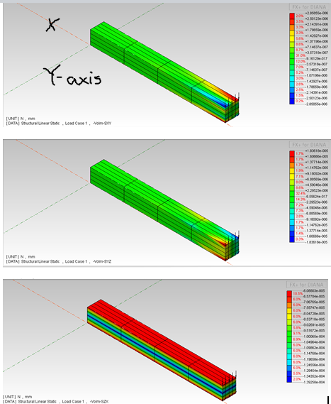
Asalamualaikum, I have applied point load on cantilever beam (Lx=1m Ly=0.1m Lz=0.1m) at its free end (1N in z direction). i have divided the load on each node at top and bottom fibre (as shown in figure). why the software showing the SXY and and SYZ stresses since they will only develop due to torsion. it should show only SZX stress which are due to shear i.e VQ/Ib. i have also put poison ratio as zero. if i change the loading condition to uniform distributed loading, then it gives SXY,SYZ=0. Thankyou attached is the file showing x and y axis of the beam. it also shows sxy, syz and szx respectively. 1 point
 -

Introduction Hafiz Athar Farooq
atharfarooq007 reacted to UmarMakhzumi for a topic
Welcome aboard Athar Farooq. Thanks.1 point -
Diaphragm Design
Hussain Abid reacted to Muneeb Badar for a topic
Dear Waseem, This is the minimum brief which I can write, otherwise if you start elaborating this you could end up with 20 or 30 pages. Anyways thanks for your appreciation......1 point -

Need Help To Make Column And Beams.
atharfarooq007 reacted to WR1 for a topic
My dear, you must hire a structural engineer for that purpose1 point -
Need Help To Make Column And Beams.
atharfarooq007 reacted to WR1 for a topic
you should hire/consult a structural engineer for that. It's not that simple to talk about it here. It involves so many things! Like what is the seismic zone, height of building, use of building, soil type, material strengths etc.1 point -
Punching Shear Of Shear Walls In Case Of Eq "important Issue"
mhdhamood reacted to Muneeb Badar for a topic
Dear mhdhamood, I ll send you. Please tell me how can I send as I do not know I can attach here........and my name is Muneeb not Mr. Muneeb and I am not too old to be called Mr. I think I should upload my picture as well.......... I think it is better if I create another topic/discussion and summarize all what we have discussed here under the title Diaphragm design and the post. It will be a complete concept regarding diaphragm design. But I do not know how to attach the documents and to how much capacity. What do you say........ Rana Waseem what do u say Thanks Muneeb1 point -
Failure In Shear Wall
Muneeb Badar reacted to UmarMakhzumi for a topic
The stiffer you make, the fun it gets!1 point