Leaderboard
Popular Content
Showing content with the highest reputation on 01/12/16 in all areas
-

Oct 26, 2015 Earthquake
UmarMakhzumi reacted to Salman Chaudhry for a topic
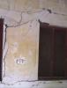
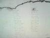
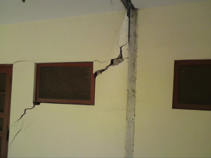
I would like to share with you guys some snaps of a building of arch.dept hostel. The subject building was constructed in 1997 and just after construction, severe cracks started propagating and made it unusable. The site selected for constructed have 35 ft fill organic material and it used to be a dump site of old Lahore. this is just to highlight the importance of geotechnical investigation and effect of differential setttlement on a small structure.
 1 point
 -

Releasing Moments At Top Of Column
mhdhamood reacted to UmarMakhzumi for a topic
Good thinking. Your understanding is correct. Thanks.1 point -
Oct 26, 2015 Earthquake
Salman Chaudhry reacted to UmarMakhzumi for a topic
You are right but structural engineering practise in general is very poor too. Anyway, we can improve on what we can do on our part. Thanks.1 point -

What Modifier Should We Take For Servicibility Check (Deflection And Drift)
Fatima Khalid reacted to WR1 for a topic
Many engineers are confused with stiffness modifiers stuff in ETABS including me. Let me add my cent here. 1. Any reasonable set of stiffness can be used as explained in ACI 318. 2. You have to determine what type of frame you are analyzing; braced or un-braced 3. Whats the analysis type? Strength, service? 4. Code allows use of 0.35,0.7 factors on inertia in chapter 10 of ACI 318 for slenderness effects. 5. Also according to code, you can use the above same model in step 4 for lateral deflections. 6. Now for lateral deflections, if the lateral load is service (like Wind load of ASCE 7-05 and previous) multiply above factors by 1.43 or 1.40 (see code). For strength lateral load like Earthquake, no need to multiply by this factor. 7. Some times you really dont need to apply modifiers at all. For example for strength design. 8. For a two-way frame with membrane slabs at top, you just need to apply 0.5 factor to beam elements. Code allows this which says for strength design you can either a. use the same modifiers as used for slenderness b. use 0.5 for beam stems only In simple words, modifiers are factors to reduce inertia for cracked sections. But if you are doing strength design, why you need the cracked inertia. And as far as serviceability is concerned, authors like Nilson even argue that a factor of 0.5 as we applied in step 8 can also be skipped because of the following reasons. a. For positive moment, beam is designed as T section but in ETABS we use rectangular section, Stiffness of T = approx 2 x stiffness of rect. So no need to apply 0.5 inertia factor to beams because T compensates for that. Just use the rectangular section in ETABS. b. For negative moments, beam is designed as rectangular, and we also model the rectangular section in ETABS. Now the cracking in this section is offset by the continuation of bottom bars into support which have stiffening effect. I hope that helps. Let me put it as a summary here; 1. Strength & service design with membranes (slab on rigid beams as compared to slabs). Beams = 0.5 or beams = 0.35 & columns = 0.7 (or whatever ratios just keep it constant). or no modifiers at all walls = 0.7 for un-cracked 0.35 for cracked 2. Strength & service design with shells (flat plates etc). beams and walls same as above slabs = 0.25 for out-of-plane m factors. just multiply above factors by 1.43 for service lateral deflections.1 point


This leaderboard is set to Edmonton/GMT-06:00