Leaderboard
Popular Content
Showing content with the highest reputation on 04/10/16 in all areas
-

Torsion: Reinforced Concrete Members
Omer Ahmed reacted to UmarMakhzumi for a topic
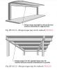
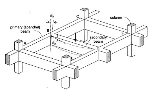
*SEFP Consistent Design* *Torsion: Reinforced Concrete Members * *Doc No: 10-00-CD-0001* *Date: May 24, 2013* Torsional forces, generally speaking, occur in combination with flexural and transverse shear forces. From a design perspective, we need to understand difference between two torsion types: Compatibility Torsion Equilibrium Torsion Compatibility Torsion Compatibility Torsion is when a member twists to maintain deformation compatibility; its induced in structural members by rotations (twists) applied at one or more points along the length of member. The twisting moments induced are directly dependent on the torsional stiffness of the member. These moments are generally statically indeterminate and their analysis necessarily involves (rotational) compatibility conditions(click on the image to enlarge). For the floor beam system shown above, the flexure of the secondary beam BD results in a rotation ǾB at the end B. As the primary (spandrel) beam ABC is monolithically connected with the secondary beam BD at the joint B, deformation compatibility at B implies an angle of twist, equal to ǾB at spandrel beam ABC, and a bending moment will develop at the end B of beam BD. The bending moment will be equal to, and will act in a direction opposite to the twisting moment, in order to satisfy static equilibrium. The magnitude of ǾB and the twisting/ bending moment at B depends on the torsional stiffness of the beam ABC and the flexural stiffness of beam BD. Now here is the fun part, the torsional stiffness of a reinforced concrete member is significantly reduced by torsional cracking. So, if you don’t design your spandrels for compatibility torsion, they will crack, increasing ǾB and reducing the induced twisting moment. To paint the same picture while using ETABS, set your torsional stiffness of the main beam to zero. This will also increase the amount of flexural reinforcement in your secondary beams. Moreover, considering design practice in Pakistan (since we never design beams without shear reinforcement), compatibility torsion can be ignored for regular structures, as minimum shear reinforcement in most cases would stand up to cracking torque. From ACI 318 commentary R11.6.1, Do note that there are some situations (such as circular beams supported on multiple columns) where both equilibrium torsion and compatibility torsion coexist. Also, eccentrically loaded beams, member curved in plan, and member of space frames will be subjected to torsion. See the attached “Timesaving-TorsionDesign-IA.pdf” as a go-by. Timesaving-TorsionDesign-IA.pdf Equilibrium Torsion In simplest words, Torsion is a limit state in this condition; a structure is subjected to equilibrium torsion when it can maintain equilibrium only by resisting the torsion. In such a case, torsional moment cannot be reduced by redistribution of internal forces since the torsional moment is required for the structure to be in equilibrium. From ACI- 318 (click on the image to enlarge). Moreover, see the structures below that defy gravity when subjected to different kind of loads by standing up to equilibrium torsion. Overall Building Torsion For overall building torsion, the torsional effects can be minimized by reducing the distance between the center of mass and center of rigidity. Center of Mass is the point where the mass of an entire story is assumed to be concentrated. The center of mass is crucial as the location of seismic force at a particular level depends upon it. The distance between the Center of Mass and the Center of Rigidity should be minimized, but may not be possible due to building geometry. Invariably, effects of torsion are present in at all buildings although analysis may show that in some buildings torsional effects are negligible.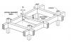
 1 point
 -
Assalam-o-Alaikum! Dear colleagues, International Building Code (IBC) 2015 edition is available online, and can be read and consulted Free of Cost, chapter by chapter, at the following link: http://codes.iccsafe.org/app/book/toc/2015/I-Codes/2015 IBC HTML/index.html Regards.1 point
-

should strap beam be monolithic with the isolated footing?
Badar (BAZ) reacted to EngrUzair for a topic
Although bottom levels of the strap and the two connected footings are generally not the same, and strap bottom level is a bit higher than the bottom face of the footings, the strap beam has to be cast monolithic with the footings. For further clarification, please see Example 16.4 (especially the last paragraph) related to the design of a strap footing according to ACI 318, at the following link http://www.chegg.com/homework-help/complete-design-strap-footing-example-164-determine-dimensio-chapter-16-problem-6p-solution-9780073293493-exc?adobe_reloaded=true:1 point -
The Most Common Errors In Seismic Design & Their Avoidance
UmarMakhzumi reacted to EngrUzair for a topic
Dear colleagues, The following article describes some of the most common errors, we may make while carrying out seismic design in accordance with ASCE 7-10 and IBC 2012. It also guides us how to avoid these errors in our future designs. http://www.structuremag.org/wp-content/uploads/2015/08/C-StrucPerform-Heausler-Sept151.pdf A somewhat different version of above article, is available at the following link: http://seaoo.org/downloads/NCSEA_Conf_Info/2014_ncsea_common_errors_in_seismic_design___how_to_avoid_them._t._heausler.pdf Regards.1 point -
Torsion: Reinforced Concrete Members
Sami Ullah Khan Bangash reacted to EngrUzair for a topic
Thanks for a good informative article on torsional aspects of RC members. However, it is suggested that references to relevant codes or documents should be complete, for easy following of information and checking back the original reference for further study. For example, it took me a while to figure out which edition was being referred to, since the year of ACI 318 being referred was missing. Accordingly, a little addition of references. The above article refers generally to section 11.6 of 2005 edition of ACI 318 (ACI 318-05). In 2008 and 2011 editions (ACI 318-08 and ACI318-11), however the relevant information has been moved to section 11.5. The quote portion, in new codes, is in section R11.5.1, and the new figure numbers are Fig. R11.5.2.1 and R11.5.2.2 respectively.1 point

This leaderboard is set to Edmonton/GMT-06:00