Leaderboard
Popular Content
Showing content with the highest reputation on 04/17/16 in all areas
-

beam moment M3 (maximum and minimum)
Sami Ullah Khan Bangash reacted to UmarMakhzumi for a topic
You are welcome1 point -

beam moment M3 (maximum and minimum)
UmarMakhzumi reacted to Sami Ullah Khan Bangash for a topic
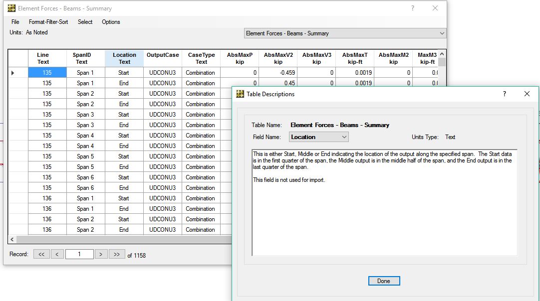
Bulls EYE!! Umar bhai your line of reasoning was right on. lol. I tried to find stuff in safe analysis reference manual but no luck. but then found this( attached in the photo below). Turns out the max and min are just end moments for each of the start, middle and end regions. I also confirmed this by moving the cursor over the bmd in those regions and comparing the values being displayed. They matched. What a relief.!! Thanks a tonne. (Y) 1 point
 -
beam moment M3 (maximum and minimum)
Sami Ullah Khan Bangash reacted to UmarMakhzumi for a topic
W.Salaam, I think the number of locations might be as per meshing for CSI Safe. I might be wrong here but when I use RISA3D, it allows me to select number of locations along where length where I want results to be reported. Normally, I choose 100 locations along beam length. Irrespective of that, the softwares report results along the length of the beam. The question is that how does SAFE define "end", "middle" and "start" regions? Like if you have 100 reporting points along a beam length, would 100/3 in the middle be reported as "middle", and other 2/3rd as "end" and "start". You will need to look up SAFE software manual for that. Let me know if the above makes sense to you or not. I will be happy to answer any follow up questions. Thanks.1 point -

Steel Column Base Plate Modelling In Sap
Sami Ullah Khan Bangash reacted to EngrUzair for a topic
I do the connections manually, using custom made Excel worksheets. However, I use ETABS for main frame analysis & design. You may develop steel connection design worksheets in MS Excel, a very powerful spreadsheet software, yet not very difficult for developing structural worksheets for routine design office work.1 point
This leaderboard is set to Edmonton/GMT-06:00