Leaderboard
Popular Content
Showing content with the highest reputation on 12/14/16 in all areas
-
.thumb.jpg.700916fbc7ead330085e15745d0270bd.jpg)
SEFP Members Gathering
EngrJunaid and 2 others reacted to Waqas Haider for a topic
Great..!!! I m only familiar with Engr Junaid because he is my class fellow, with Umar Makhzumi Bhai, and With Waqar Saleem Brother. Today I came to know what is full form of BAZ And he has changed his looks also. By the way, I used to think Engr Uzair Sir quite younger but he is quite senior to us. Mostly people after getting senior does not use social media forums much.. especially for responding people.. Really nice to know the members. This forum is really great.!!3 points -

Assign pick up column in Etabs
UmarMakhzumi reacted to EngrUzair for a topic
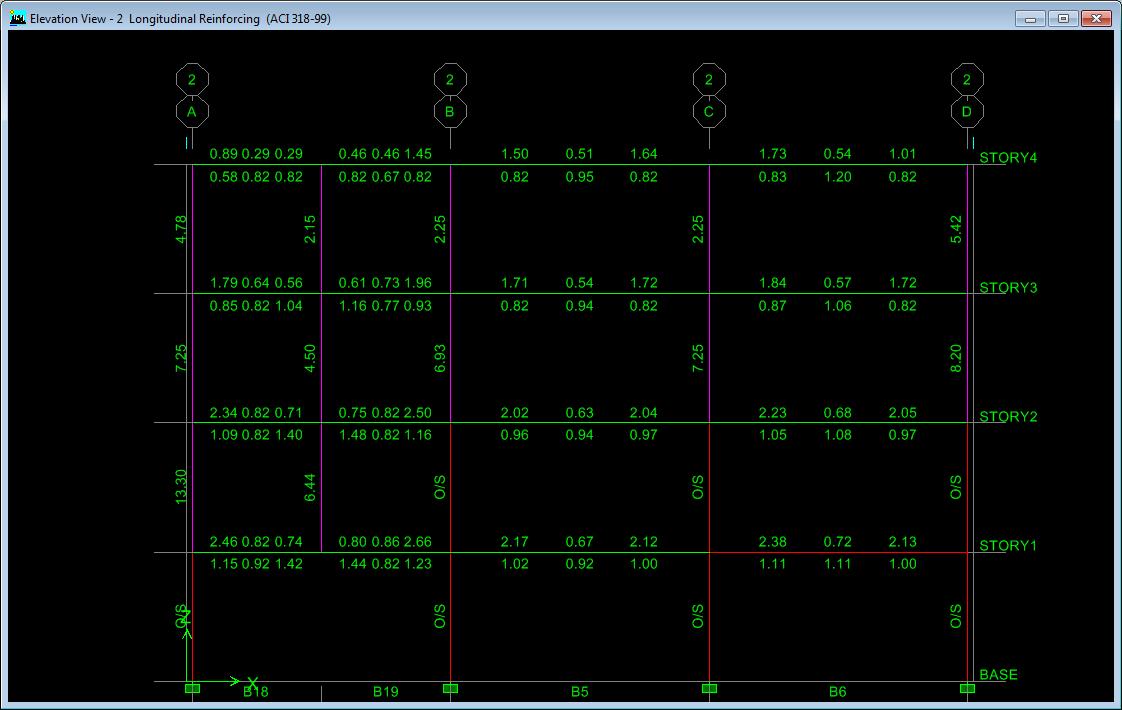
In case you have subdivided the beam (that is supporting the lowest picked-up column) correctly for creating the support point of picked-up column, it is unlikely that you don't get the beam design or reinforcement. It appears that you might have missed something or made some mistake in your model. See the attached image (taken from an ETABS 9 model, I have created to cross-check the results) and note the reinforcement of the left side beam (supporting the picked-up columns), as well as for the supported columns at all levels.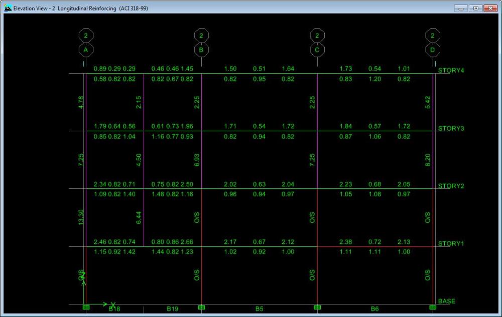 1 point
 -
Raft Modeling In Etabs
RASHEED reacted to Waqas Haider for a topic
If you are having a geotechnical report with you, there must be clearly stated value of spring constant with the name Modulus of Subgrade Reaction. Incase soil investigation have not been done on site for any reasons, you can use a tentative value for k by following relation. k = 3 x qa x 12 (in FPS in k/ft3) k = 3 x qa x 40 (in SI in KN/m3) where qa = allowable bearing capacity. and 3 is Factor of safety applied on soil while determining bearing capacity of soil. For the reference of this formula, please read the attached document. Correlation_BC_and_K.pdf1 point -
Help required for analysis in etabs
Waqar Saleem reacted to EngrUzair for a topic
There may be several reasons for this. For example, - provided columns are of a larger size, or - there are a number of shear walls, or - you might have erroneously assigned support property to the column joints at all storey levels, instead of those at base level, etc. You should recheck your model carefully to determine, what might be the real reason for the results obtained. Assigning of diaphram is necessary for proper accounting of stiffness of the structure, to resist lateral forces (earthquake etc). Meshing is essential for the transfer of slab load to the edge beams more uniformly. HTH1 point -

SEFP Members Gathering
EngrUzair reacted to Waqar Saleem for a topic
Salam . from left to right Mr.Junaid Shah, Mr.Asad Ishaq, Mr.Uzair , Mr.Umar Makhzumi (Admin), Dr.Badar Ali Zeshan (Moderator), Mr.Abdul Qadir, Mr.Waqar Saleem(Moderator) Regards1 point -
ETABS And SAFE issue
UmarMakhzumi reacted to Waqas Haider for a topic
You must export combos related to all loads i.e. gravity and lateral loads because ultimately effects due to all the loads is going to be transferred to foundation. Designing foundation only for gravity loading is not correct approach. But remember, since mostly bearing capacity provided by Geotechnical consultant is safe bearing capacity instead of ultimate bearing capacity (safe bearing capacity means full factor of safety has been applied to bearing capacity as we do in ASD approach). Hence if we use this bearing capacity for design of foundations, loading combos of ASD or unfactored loading combos must be used. UBC and IBC provides these laod combos and footing must be designed for all this loading combos instead of autogenerated loading combos of ETABS which are factored. Either define these loading combos in etabs and export to safe or directly define then in safe. Increase of bearing capacity upto 33% is not allowed in all the cases. It can only be used where in loading combos having two or more variable/Transient loads togather, we have not reduced the intensity of transient loads. If we have reduced these loads by 0.75 factor then bearing capacity can not be increased by 33%. Basically it is not the case with bearing capacity only. Any strength determined by using ASD approach (i.e. full factor of safety applied on strength of member, ) can be increased by this approach but only if in loading combos transient loads have not been reduced. UBC and IBC proposes two types of loading combos for ASD. in first type of combos you may find for example a combo D+L+W and in 2nd type you can find the same combo as D+0.75L+0.75W. if you use first type of combo you can increase by 33% and if u r using 2nd type of combo, note that the loads have been reduced by 1/1.33 = 0.75 times instead of increasing strength. so same factor of 1.33 has been applied on load side so in this case no increase can be made in strength. For a detailed study refer to following document. 1-3rd stress increase AISC.pdf1 point -
Assign pick up column in Etabs
UmarMakhzumi reacted to EngrUzair for a topic
Picked-up columns are supported on beams at their lowest point. In order to draw a picked-up column, you will need to create point objects at required location on the relevant beams, and connect the two points (one located on the lower level beam and the second on the next upper level beam) with a line element (defined as a column member). Application of loads, and analysis & design is similar to the other normal columns of a frame structure. HTH1 point -

What Modifier Should We Take For Servicibility Check (Deflection And Drift)
Fatima Khalid reacted to WR1 for a topic
Many engineers are confused with stiffness modifiers stuff in ETABS including me. Let me add my cent here. 1. Any reasonable set of stiffness can be used as explained in ACI 318. 2. You have to determine what type of frame you are analyzing; braced or un-braced 3. Whats the analysis type? Strength, service? 4. Code allows use of 0.35,0.7 factors on inertia in chapter 10 of ACI 318 for slenderness effects. 5. Also according to code, you can use the above same model in step 4 for lateral deflections. 6. Now for lateral deflections, if the lateral load is service (like Wind load of ASCE 7-05 and previous) multiply above factors by 1.43 or 1.40 (see code). For strength lateral load like Earthquake, no need to multiply by this factor. 7. Some times you really dont need to apply modifiers at all. For example for strength design. 8. For a two-way frame with membrane slabs at top, you just need to apply 0.5 factor to beam elements. Code allows this which says for strength design you can either a. use the same modifiers as used for slenderness b. use 0.5 for beam stems only In simple words, modifiers are factors to reduce inertia for cracked sections. But if you are doing strength design, why you need the cracked inertia. And as far as serviceability is concerned, authors like Nilson even argue that a factor of 0.5 as we applied in step 8 can also be skipped because of the following reasons. a. For positive moment, beam is designed as T section but in ETABS we use rectangular section, Stiffness of T = approx 2 x stiffness of rect. So no need to apply 0.5 inertia factor to beams because T compensates for that. Just use the rectangular section in ETABS. b. For negative moments, beam is designed as rectangular, and we also model the rectangular section in ETABS. Now the cracking in this section is offset by the continuation of bottom bars into support which have stiffening effect. I hope that helps. Let me put it as a summary here; 1. Strength & service design with membranes (slab on rigid beams as compared to slabs). Beams = 0.5 or beams = 0.35 & columns = 0.7 (or whatever ratios just keep it constant). or no modifiers at all walls = 0.7 for un-cracked 0.35 for cracked 2. Strength & service design with shells (flat plates etc). beams and walls same as above slabs = 0.25 for out-of-plane m factors. just multiply above factors by 1.43 for service lateral deflections.1 point -
Raft Modeling In Etabs
Hussain Abid reacted to WR1 for a topic
For raft in ETABS or SAFE you will use area springs. You can assign springs by going to this menu Assign>Shell/Area>Area springs. You can also use point springs instead of area springs, but for that you have to multiply area spring stiffness value by the tributary area on that specific node that means if your mesh is not regular, you have to calculate point spring stiffness value for each spring1 point