Leaderboard
Popular Content
Showing content with the highest reputation on 02/20/17 in Posts
-
It might be this; "For concrete frame design using the ACI 318-08 and ACI 318-11 codes, the design report for "Shear Details" has been enhanced for "Sway Special" frames by adding the field Design Shear (Vu) for clarity. Previously, only the factored Vu was reported, which may not be the governing force for capacity design." Incident Id: 64173 in ETABS 2013 13.1.4 enhancement user notes.2 points
-

reinforced concrete longitudinal rebar placement
UmarMakhzumi reacted to WR1 for a topic
Depends on design moment combination. Thats why i always recommend putting in the right reinforcement in columns in ETABS and put it on 'check' instead of design.1 point -

Design life of RC structures
EngrUzair reacted to UmarMakhzumi for a topic
I don't have a reference from Canadian Building Code, but I have seen a design life of 50 years in client specifications. Also, to me this is what is the basis is in design clauses (like Maximum Considered Earthquake is based on 2% probability of being exceeded in 50 years, or wind/ snow design loads are based on 50 year cycle). For Pakistan, it should be same as international code. In Canada, even though design life is specified in the documents, I have seen engineers continue to retrofit or modify existing structures which have passed the 50 years mark as long as field tests done to see the condition of concrete/ steel come acceptable. We have got a bridge in Edmonton that was built in 1915. It has been retrofitted and continues to serve the community. Thanks.1 point -

Stability of Multiple Flexible Towers with combine Stiff Podium
Waqas Haider reacted to EngrJunaid for a topic
(1). Structure Aspect Ratios The Horizontal/plan aspect ratio (Length to Width ratio) of the side block is 160/18=8.8 While its vertical/slenderness ratio (height to width ratio) is 60/18=3.33 I didn't come across any code limitations regarding these ratios But an indian research paper "Effect of Aspect Ratio & Plan Configurations on Seismic Performance of Multistoreyed Regular R.C.C. Buildings: An Evaluation by Static Analysis" concludes that, (a) The buildings with Horizontal Aspect Ratios 4 or less than 4, the seismic performance is reasonable. Above this, the worse effects of excessive forces, storey drift and displacement values may be obtained. Hence they should be discarded due to their unsatisfactory, weaker and unreasonable performances on the bases of above seismic parameters, which can cause detrimental and disastrous effects or otherwise be treated with the enough earthquake resistant elements. (b) The buildings with Vertical Aspect Ratios less than 4, the seismic performance is reasonable. Above this, the worse effects of excessive overturning, storey drift and displacement, period of vibration, etc. values may cause detrimental and disastrous effects to the buildings. Hence slender building configuration, as far as possible, should not be chosen, or otherwise be provided with the adequate earthquake resistant solutions. (2). Flexible Tower on Rigid podium UBC-97 Section 1629.8.3 item 4 says "Structures having a flexible upper portion supported on a rigid lower portion where both portions of the structure considered separately can be classified as being regular, the average story stiffness of the lower portion is at least 10 times the average story stiffness of the upper portion and the period of the entire structure is not greater than 1.1 times the period of the upper portion considered as a separate structure fixed at the base." And UBC-97 Section 1630.4.2 Item 2 says 2. The following two-stage static analysis procedures may be used for structures conforming to Section 1629.8.3, Item 4. 2.1 The flexible upper portion shall be designed as a separate structure, supported laterally by the rigid lower portion, using the appropriate values of R and ρ. 2.2 The rigid lower portion shall be designed as a separate structure using the appropriate values of R and rho. The reactions from the upper portion shall be those determined from the analysis of the upper portion amplified by the ratio of the (R/ρ ) of the upper portion over (R/ρ ) of the lower portion.1 point -
Applying triangular load on plates/shells in ETABS or SAP200
Howard Roark reacted to WR1 for a topic
You can do like this; What you have to do is to note down the z coordinate of each shell element along the height (in Excel e.g.) and calculate the force at top and bottom node of each element, then apply the average pressure in local axis 3 (plus or minus). Tip: Always model retaining walls/swimming pool etc so that all the walls have local 3 axis either inside the pool/container or outside. So you can select all the walls once and apply the pressure in one go. And for that turn on 3d view in XZ or YZ in ETABS and select top most mesh, apply pressure and so on. Its not that difficult. To calculate average pressure you can either make your own excel sheet or use the following I once made. Water Pressure on Walls in ETABS.xlsx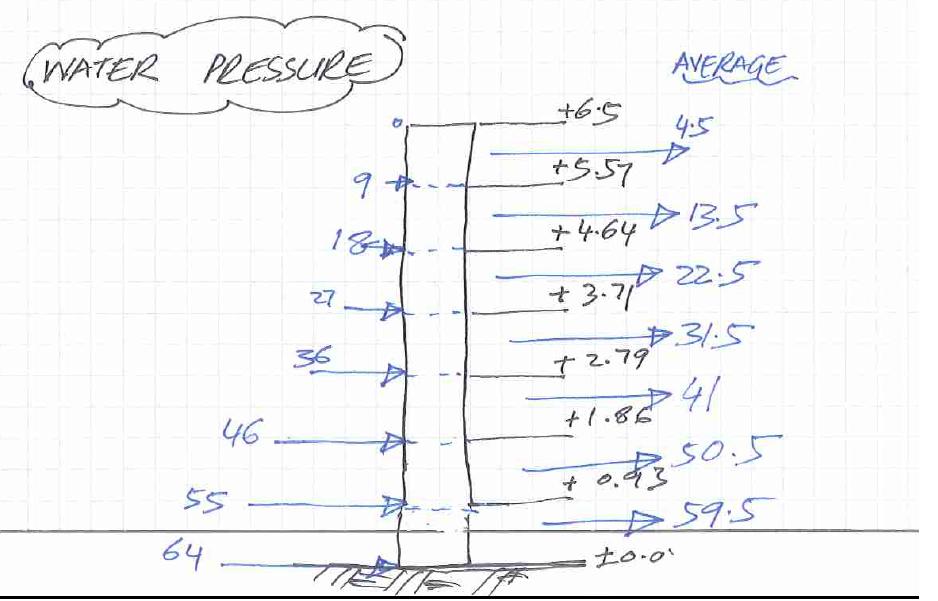 1 point
This leaderboard is set to Edmonton/GMT-06:00