Leaderboard
Popular Content
Showing content with the highest reputation on 05/14/17 in all areas
-
.thumb.jpg.700916fbc7ead330085e15745d0270bd.jpg)
RCC Dome Design
UmarMakhzumi and one other reacted to Waqas Haider for a topic
A very interesting and explanatory document along with example..... design of dome.pdf2 points -

Combined Torsion and Shear Beam failure in ETABS
Hafsa Azmat reacted to WR1 for a topic
Dear Bhuvan, Instead of overtly throwing your models at us, you could have explained the problem in more detail may be with some snapshots. We all are working in different places, and you could imagine it is not always possible to open some third party models/files/work during working hours. Please try searching the forum for the similar questions and try to limit the problem with your own research and searching skills utilizing the past posts in this forum. If still you do not get the answer, please try uploading a snapshot or two of a specific beam in your model explaining your concern.1 point -
1997 Ubc Vertical Earthquake Term Ev
Badar (BAZ) reacted to WR1 for a topic
Another thought; 1. Vertical effects are not required in ASD analysis of UBC-97 but are required in ASCE 7-05. 2. Inclusion of vertical effects make no sense according to Gary R.. Searer; SEAOC adopted the concept of vertical effects for the sole purpose of adjusting the seismic design in line with 1.4D factor of dead loads in earlier codes. This factor was changed to 1.2D due to better approximation of dead loads in the new codes. So in order to rule out the discrepancies vertical effects were introduced. "Certain unintended consequences of this action were only discovered after the code was published"... For example one design that was safe in ASD suddenly became unsafe in strength design combinations. In near-fault areas of Ca=0.6, resistance to overturning decreases by a huge margin to 60% of dead loads. The author explains that; With the exception of a single story structure, ignoring live load totally in the resisting load combination is very very conservative. In order to accelerate portions of the building rapidly upward, the upward forces must exceed gravity by a large amount, thus resisting weight is significantly greater than just 1.0 dead load. The problem became more complicated with the inclusion of vertical effects in ASD in ASCE 7-05 in a try to align the ASD design with strength design as far as vertical effects were concerned. He recommends using 1.2D +- E + f1L + f2S or 0.9D +- Eh. Refer to: 2006 Annual Meeting of the Los Angeles Tall Buildings Structural Design Council Alternative Procedures for Design of Tall Buildings POORLY WORDED, ILL-CONCEIVED, AND UNNECESSARY CODE PROVISIONS Gary R. Searer, S.E. Consultant Wiss, Janney, Elstner Associates, Inc https://www.scribd.com/doc/285836953/Poorly-Worded-Ill-Conceived-and-Unnecessary-Code-Provisions1 point -
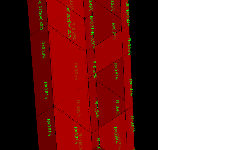
Shear wall design
Jairo González reacted to Waqas Haider for a topic
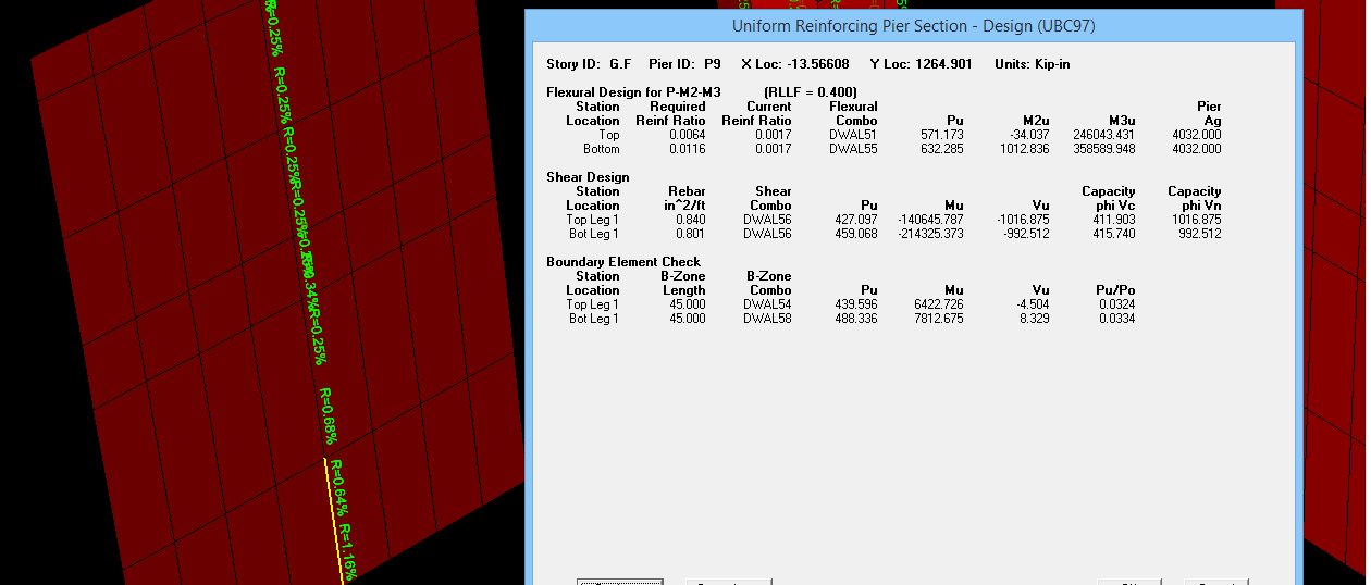
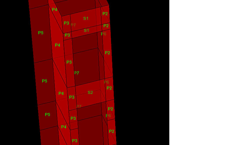
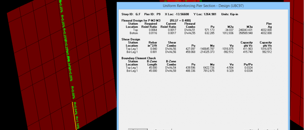
Last month, i design a structure with shear walls. I will attach more documents. What i know/remember i will share with you. In simple, Pier is similar to column and Spandrel is similar to beam. Shear wall is modeled in etabs as shell element. You are to assign it either pier label or spandrel label (Depending on situation of shear wall) to design a shear wall. If you want to design a shear wall, it mostly needs peir label to be assigned. But for the portions of shear wall above openings, as its behavior is somewhat like beam resting on two supports, you need to assign it a spandrel label. I have attached screen shots of my model where you can see i have assigned pier label to the vertical elements and i have assigned spandrel labels to the elements spaning horizontally above openings. The reason behind is detailing based. The detailing in vertical elements of shear wall is similar to wall (or column) and its design is based on considering it as an element resisting majorly AXIAL FORCES + MOMENTS along with inplane shear forces. (Theoratically it acts as a cantilever beam spaning vertically which again represent behavoiur similar to column). I have also attached screen shot of design detail of pier which reports total vertical steel in wall with respect to section area for resisting moments, horizontal steel for resisting shear and some times boundry elemtns (i.e. special detailing at ends of shear wall exactly as in column i.e. shear rings confining vertical bars). I have also attached screen shot of design detail of spanderal which reports top steel, bottom steel, to resist moments similar to beam and vertical steel to resist shear along with DIAGONAL reinforcement some times needed to account for reversal of forces. I will attach more documents throwing detailed light on shear wall design i found few weeks ago. Also my model is attached (it is in seismic zone 4 from where you can get idea about pier labeling and spanderal labeling) One important thing is that, pier label and spanderal label also meant to integrate forces. i.e. if you assign same pier label to all walls in a floor connected with each other, the software will report results only for one and critical wall because all walls were assigned only one pier label. If you want to have multiple outputs at multiple walls, you should assign them different pier label. in image number 5, note that i have not assigned any pier to the selected portion of wall. hence no reporting of results is done. Etabs Center Portion.e2k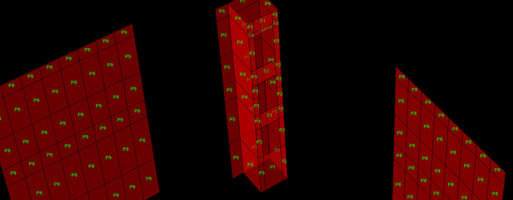

 1 point
 -

Shake table testing for Buckling Resistant Braced frame
Waqas Haider reacted to Fatima Khalid for a topic
Shake table test for Buckling Resistant Braced frame is conducted in NEDUET today at Department of Earthquake Engineering.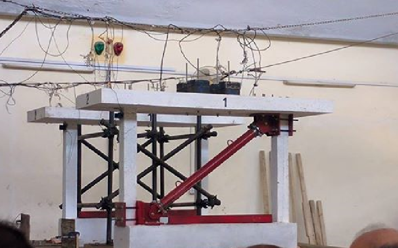 1 point
 -

Building Joint Displacement/ Drift in Etabs
Waqas Haider reacted to Badar (BAZ) for a topic
After running the analysis, one way is to look for the symbol that is used for displaying the deformed shape of your structure. The deformed shape will be displayed against a load case, or load combination. Once you have deformed shape, right click on the node where you want displacements. Limits are already discussed in the forum. Use the search facility, either on google, or in the forum.1 point