Leaderboard
Popular Content
Showing content with the highest reputation on 04/22/21 in all areas
-
 AOA everyone. Recently I've been very confused with development length and how its provided in different components. I have a few conceptual confusions about it and then a few practical and design aspects of it. I'd really appreciate help on these. Do we provide/check development length for simply supported beams (i.e. check it past the max moment?) Where do we need to check for development length? (in my understanding, we need to check it almost everywhere, where you need to ensure full moment capacity) What is a "critical section" when we talk about development length? (refer to the attached picture) I think its the point beyond which we need to ensure development At a wall-slab joint where both the slab and wall are 8" thick, if #6 bars at 8" c/c need to be developed from the slab into the wall, I found that even with the 90 degree hook, the development length is at least 14". How do you satisfy development length in such a case? For hooked development length ldh, is it the length up to the hook or is the length that includes the length of the hook? For example for a 90 degree hook, would it be 12db+the length beyond the critical section or just the length beyond the critical section up to the hook? I've seen in a few places on the internet that people include the 12db into the development length. This stuff has been eating up gray matter from my brain for a few days now. Any help is appreciated. Thanks!
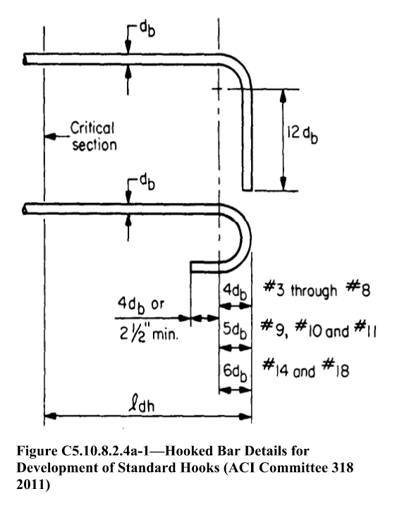 1 point
 -

Dual System Check in ETABS
Wajahat Latif reacted to UmarMakhzumi for a topic
Your case is tricky. Your shear walls will still resist load but differently. To see that happening, you will need to model the stair slab (diagonal & Landing). Also please see this thread: Thanks.1 point -

Stiffness Modifiers for Pick Up Columns
Kamranullah reacted to Wajahat Latif for a topic
Here is the pick up column modeled in Etabs. To ensure this in the field, we would need to provide a pin-connection detail, correct? A mesnager hinge would probably do. Do you have any details on that? Have you seen that in any project? Thanks. 1 point
 -
 There are typical details of reinforcement, which can be found in various detailing manuals, that the design engineers follow around the world. They do not normally check development length for typical/usual member sizes with usual/ conventional loadings, instead they follow those reinforcement details. The critical section is the section with maximum tensile stress. For most beams or flexural members, it is the face of column or support. For this particular case, you can treat the wall-end as simply supported. But, there are other ways to develop the reinforcement such as mechanical anchorages (headed bar) or welding with end-plates. As you can see in your attached diagram, the length of hook is not considered by American codes. Some codes do consider them explicitly. For American codes, any length beyond 12db does not contribute.1 point
 -
Stiffness Modifiers for Pick Up Columns
UmarMakhzumi reacted to Badar (BAZ) for a topic
Yes, it is. You can also release rotational restraint at the the end of landing beam.1 point -
Important questions about RSA
UmarMakhzumi reacted to Wajahat Latif for a topic
This topic troubled me a lot the last few months so I came across this post while doing my research. A quick update to the consideration of accidental torsion effects in RSA: the dynamic mass shifting procedure has been prohibited by Supplement # 2 to ASCE 7-16. Latest research found that buildings designed with this procedure were more susceptible to collapse. Now we're only left with the static method of accounting for accidental torsional effects in RSA (including amplification). To accomplish this in ETabs, we can find the amplified eccentricities along both X and Y axes from the regular ELF analysis. These amplified eccentricities are input in the RS-X and RS-Y load cases respectively. I confirmed this approach with Dr. Justin Marshall, the co-author of "Guide to Seismic Provisions of ASCE 7-16", and Engr. Aung, Director AIT Solutions. As WR-1 said, Etabs (link) will obtain accidental torsional moments from story forces obtained from the combined RSA, then add these forces to the combined RSA results. This is the procedure prescribed in the "Guide to Seismic Provisions of ASCE 7-16" as well, snippet attached. Omission of consideration of amplified accidental torsional effects in RSA results in very weak designs, and this is prescribed in both ASCE and UBC-97. Note: the dynamic mass shifting analysis is still applicable for linear response history analysis. However, for response spectrum analysis it is prohibited.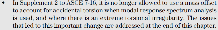
 1 point
 -
Dual System Check in ETABS
UmarMakhzumi reacted to Wajahat Latif for a topic
Hi Arslan, just browsing through your posts. You might already have the answer to this. To check if the columns are able to resist atleast 25% of the lateral force, you should do the following: - Go to Mass Source and change the factors to 0.25 instead of 1. This would reduce the seismic base shear to 25%. - Change your shear wall f12 modifier to nearly 0, i.e. 0.0001. This would mean that your shear walls will not resist any lateral forces. That is, all the lateral force will be resisted by columns only. - Check if your columns are able to resist the lateral loads. If reinforcement in your columns is not exceeding 4%, you're good. - I would save this as a separate model and provide the maximum reinforcement in columns from this model and the original one.1 point -
Overcome Story Drift
Kamranullah reacted to UmarMakhzumi for a topic
Depth will help for the case of moment frame. Width can have a very minor to negligible effect as contribution of beam width to moment of inertia is small.1 point -
Multi-tower building with common podium in Etabs
Howard Roark reacted to Wajahat Latif for a topic
Here is a response that I received from Engr. Aung, Director AIT Solutions. Sharing for everyone's knowledge. "You can consider the podium, Tower 1 and Tower 2 to be three different "towers", using multiple towers option. T3 is podium (Foundation to 3rd floor), T1 and T2 are Tower 1 and 2, starting from 4th floor to roof. However, it is suggested NOT to use ELF base shear from analysis if you have multiple towers in the model. Normally, ELF base shear for each tower above the podium is calculated manually for scaling purpose only. To determine the base shear for scaling of two towers resting on a common podium, it is suggested to compute the design base shear of each tower above the podium (using weight of tower above podium) based on code-specified equations manually. Then, scale the base shear of each tower above the podium in a 2-tower combined model in different response spectrum cases. You will have two sets of response spectrum cases: RSX-T1 and RSY-T1; RSX-T2 and RSY-T2. Use 2-tower combined model to design each tower with corresponding response spectrum cases. For podium design, you may use the envelope of those cases. For application of wind load in multiple towers, it is suggested to turn on "Allow multiple towers" in the Option menu and assign the diaphragm names separately for each tower. If the story height of each story is different between two towers, it is suggested to crosscheck the wind base shear of each tower above the podium with manual calculated results. It is okay to connect two towers on a common podium. It is suggested to check the in-plane forces in podium diaphragm due to movement of towers under lateral loads. If the seismic gap is allowed at the amenity podium floors and no constructability and maintenance issues, you can also provide the seismic gap and analyze the towers separately."1 point -

Important questions about RSA
UmarMakhzumi reacted to WR1 for a topic
I guess you are talking about modal super-position, but that is not my question. Yes and according to SK Gosh (http://skghoshassociates.com/SKGAblog/viewpost.php?id=5), we need to amplify dynamic torsion because; ".... accidental torsion is not determined as part of the dynamic analysis, but as the result of a separate static load applied at an eccentricity. The only way we can use the exception [to ignore amplification in dynamic] is to incorporate the accidental torsion effects into the building model itself by defining a floor mass distribution that is not uniform so that the center of mass has a 5% offset from the centroid of the floor area." Agreed. Now, the next step is to how to do it practically. We are not just talking about the concept but to actually do it. Now, see CSi ETABS Wiki (https://wiki.csiamerica.com/display/etabs/Accidental+eccentricity) 1. In the first method, accidental torsion is included in dynamic analysis by actually shifting CM as SK Gosh suggests that would change the dynamic properties, natural characteristics and stiffness matrices for each eccentricity and so we do not need to amplify further, because accidental torsion has been calculated through dynamic analysis. Con: The main drawback is that as the properties of model change for each eccentricity, hence 4 separate eigenvalues analyses must be performed for each eccentricity and then finding a way to envelope the maximum response of these 4, which is not possible in majority of software. What is the simple solution? See point #3. 2. Second way is to model a static torsional load [or a static force applied at an eccentricity] at each story for each eccentricity to approximate these effects. Then static + dynamic response is combined. This is where we need to amplify accidental torsion. Because accidental torsion has not been calculated dynamically. 3. An "efficient and practical" approach is adopted in ETABS. After the analysis of MRSA cases; a. Acceleration at each node is multiplied by tributary mass and given eccentricity so the result is a torsional force = m.a.e = F.e b. A static response is generated under these torsional loads and added to MRSA dynamic results. Now, strictly speaking, eccentricity was not directly analyzed in dynamic analysis in method 3 but atleast there is a satisfying globally used practice. So we dont need to increase accidental torsion by this method. 4. There is another method developed by Fahjan et al. and quoted by CSi wiki. It also contains good background information. You can view the paper from csi wiki page.1 point -
 Dear Rana, Please check the reference from ETABS Concrete design manual. This is what I am saying. Thanks Muneeb
 1 point
 -
Beam Fail In Torsion And Shear In Etabs Then Why Torsion Modifier Reduce To 0.001
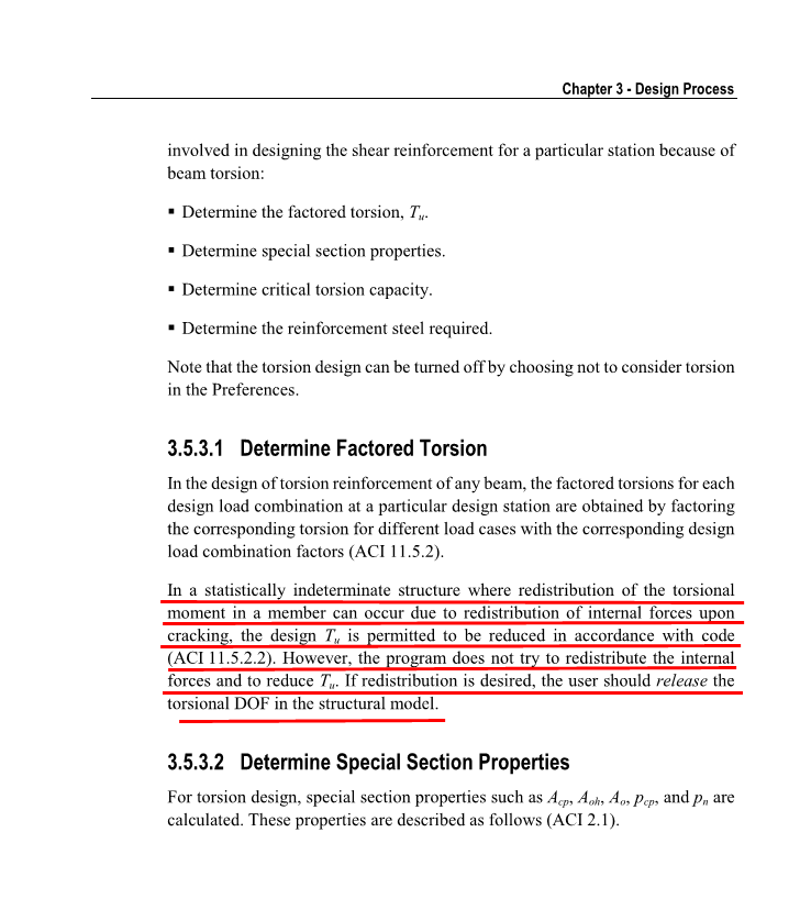
Waqar Saleem reacted to WR1 for a topic
In my understanding these are NOT 2 different methods; This is just a differentiation; There are two torsions; 1. Compatibility torsion (where redistribution of moments take place) like slab on beams 2. Equilibrium torsion (where there is no path available for redistribution of moments, like a cantilever slab resting on a beam) These are not two different methods of analysis in ACI or ETABS. This is just to distinguish the cases. That is why it does not matter in ETABS because in ETABS loads will follow the paths that is available. So does not matter if it is case 1 or 2, apply J modifiers but watch for slab moments. Also make sure your detailing handles all these issues. For example if the beam is torsionally too stiff as compared to slab, it will take more moment as compared to slab, and if you are applying less J modifier to beam then make sure the detailing also follows the same approach. (try to increase bottom reinforcement of slab).1 point