-
Posts
1471 -
Joined
-
Last visited
-
Days Won
447
Content Type
Profiles
Forums
Events
Everything posted by UmarMakhzumi
-

Modelling Steel Truss with Overhang on ETABS
UmarMakhzumi replied to sochtheking's topic in Steel Design
For trusses, all members should be pinned but any cantilever members that go beyond the support should be modelled, designed and detailed as continuous/ moment connections or else the system would be unstable. What are your boundary condition for these truss members that cantilever? Thanks. -
Blinding is not designed, also its use is not structural as the only purpose for it is to provide an even surface and avoid mud pools during rain when the foundation pits are open. You can achieve the same with compacted gravel. Thanks.
-
My pleasure Ayman. One way to solve this would be to measure force causing this ambient vibrations using strain gauges that measure strain in structural members that can be convert back to force .. This will involve some assumptions and simplifications as well. Thanks.
-
A mode shape can provide you with displacements. For simplicity, F= KX, With F (force) and X (displacement) provided, K can be figured out. What do you say.. I am thinking out loud here. Thanks.
-

Design of shell element for masonry brick bearing wall in Etabs
UmarMakhzumi replied to ALI-KARIM's topic in Concrete Design
ETABS is not suitable for masonry design. -
WSalaam, This is a good question. However, the attached document is for structural plain concrete but blinding concrete is categorized as non-structural concrete. you can even replace it with well compacted gravel. Thanks.
-

Slab parameters for Open Grid Steel Flooring in ETABs
UmarMakhzumi replied to Osama Anwar's topic in Seismic Design
Wsalaam! This is basically "Steel Grating" sitting on steel structure. I personally think its not appropriate to call it Open Grid Steel Framing System. The standard industry practice is that we don't model the grating. You can consider the weight of grating based on manufacturer's catalogue (you can google if you don't have any, as this data is very common). Grating spans one-way and you can calculate the load based on its span. Normally you will need to provide in-fill beams to meet span requirements against occupancy loads. The steel that supports this grating will need horizontal (plan) and vertical bracing. Normally for steel, the beam to column connection in major axis is moment, and braced frames are used in minor axis. Very common. Thanks. -
HI @JL07, I am working on a US job right now and we do include the live load, anchor load with dead and seismic. I am not sure how exactly the code words it out but its standard practice in the company I work for reasons explained above. Seismic LC's (for drift) are without redundancy factor and deflections from LCs are amplified by multiplying the deflection to Cd/Ie. Hope that helps. Thank you.
- 24 replies
-
- wind story drift limits ubc
- drift
-
(and 1 more)
Tagged with:
-
For this model, you can just model the RCC and apply the wind load on RCC and from masonry wall to it. No need to model masonry. Thanks.
-
Hairline cracking is not bad but actually good. It means that load is transferring from concrete to steel. You can measure the crack width. If it is surface or harline cracks, then it should be fine. Thanks.
-
You can measure the deflection by using a thread and putting it across the floor and then seeing if floor is lower than the thread. Anyway, if the reinforcement works, that's fine. If it doesn't you should retrofit the beam. Thanks.
-
WSalaam, Cracking is not always bad. If J were you, I would re-check the design, get site reports on concrete strengths, confirm site placed rebars met development lengths and if all that works would let it go. Also other items you can do is to monitor deflection and get some NDT done if site information can’t be trusted. I am not sure about your comments on column orientation. Thanks.
-

Design of shell element for masonry brick bearing wall in Etabs
UmarMakhzumi replied to ALI-KARIM's topic in Concrete Design
WSalaam.. Ali-Karim, please see this post for stiffness modifiers reduction. Please note that I am not sure if your approach will provide sound results for masonry design. Thanks. -

ETABS - Global axis sign convention for base reactions
UmarMakhzumi replied to JL07's topic in Software Issues
Hi JL07, I don’t have any CSI softwares installed but a quick way would be to model a simple column with fixed base and apply a moment to it and see how reactions are reported. I assume the right hand rule is being followed for +ve values but that’s my guess.. Do let me know if that works. Thanks. -
Hi JL07, Please see the article below. It should answer your question. These days I am working on a US job, so if you can’t find your answer in the article below, let me know and I will answer the question in detail. It’s just I am away from computer right now. https://www.structuremag.org/?p=14696 Thanks.
-
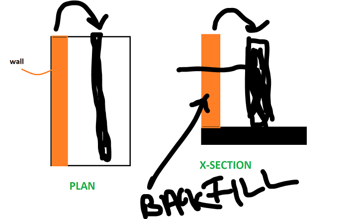
Abbas, The literature is clear, if it is outside, it is unstable. You need to make it inside or equilibrium won't hold. Negative reinforcement will design the slab to take the moment but the "geometric sizing" will prevent overturning. Presence of reinforcement doesn't add to stability. Simplest solution would be move the wall inside and use backfill to counterbalance any overturning. Other solutions can be pouring a raft. Hope that helps.
-
Wsalaam, This has been extensively discussed in this forum. Please search "Backstay effect" and "Location of Base for Seismic". Thanks.
-
This is a very good question. Generally speaking, Areas of interest are highlighted by structural engineer but number and location of bore holes is suggested by Geotechnical Engineering keeping structural in the loop. Number of bore holes depend upon consistency between different boreholes (once they drill boreholes and if the data is not consistent, then they might need to drill more), type of structure (some structures are very sensitive to settlement, like Large LNG Tanks) so a lot of bore holes would be done for a tank foundation than for other equipment foundation etc. Experience and engineering judgement also play a part. To sum up, Site variability in geotech info and Structural Sensitivity to geotech info are the major factors. Thanks.
-

Moment resistance of Pinned/Hinged structure?
UmarMakhzumi replied to Omer Ahmed's topic in Students Zone
If reinforcement is there, you should consider it fixed. Thanks. -

R.C.C Slab Failure
UmarMakhzumi replied to Engr. Arslan Raza's topic in Engineering Marvels & Disasters
Wsalaam.. First, we need to understand why this happened. 1) Was this because the existing design was inadequate. -> You need to do validate existing design to check this. 2) Was this because the construction wasn't as per the design. -> I doubt you will have any construction record so you need to see photos of construction if available to make sure the lengths were right. Get some additional NDTs to confirm rebar size, spacing, cover, concrete strength to figure out the problem. 3) Based on above you, you can suggest the path forward. Hope that helps. -

Best University For MSc. Structural Engineering
UmarMakhzumi replied to Engr. Arslan Raza's topic in Students Zone
Good luck and also it is great to have initiatives like you did. You can also work part-time with someone to get design experience and then start expanding your services. There are a lot of engineers on this forum that you can contact and engage for peer review. A lot of firms do that. -
You can watch this:
-

Pick Up Columns - Column Connection to Slab
UmarMakhzumi replied to Muhammad Hashmi's topic in General Discussion
I have done a lot of these using Canadian Code. In older versions of ACI, Appendix D in ACI 318 used to cover all the limit states (mentioned by Baz above as well). I don't know what is in the latest version but you calculate your loads including moments if any, and then calculate the minimum embedment capacity for different limit states against applied loading using ACI Appendix D. If you are using Hilit, they have a free software called Profis Anchor that can do all the calculations for you. Just download and provide your rebar configurations, concrete edge distances and loads and it will calculate the embedment using Hilti Products. Thanks. -
There is no basis to the statement. You should develop it fully or if it is not developed fully, you should check for both extreme possibilities (that is, considering it is pinned). Such assumptions still work because of re-distribution of forces and that there are a lot of approximations in our analysis. Thanks.
- 12 replies
-
- hooks
- reinforcement detailing
-
(and 1 more)
Tagged with:
-
You're welcome. There is also a minimum hook development length requirement - the As required/ As provided can't reduce it beyond that amount. I don't remember what is in ACI, but you can look it up. Also this might be unlikely as moment needs to be developed at the face of the wall but who knows what they were thinking. There might be a reason. Thanks.
- 12 replies
-
- hooks
- reinforcement detailing
-
(and 1 more)
Tagged with:


