-
Posts
1470 -
Joined
-
Last visited
-
Days Won
446
Content Type
Profiles
Forums
Events
Everything posted by UmarMakhzumi
-
This might give you some clues: Thanks.
- 20 replies
-
- pin support
- fixed ends
-
(and 1 more)
Tagged with:
-

Electric/ Signal Pole foundation design guideline
UmarMakhzumi replied to hani's topic in Foundation Design
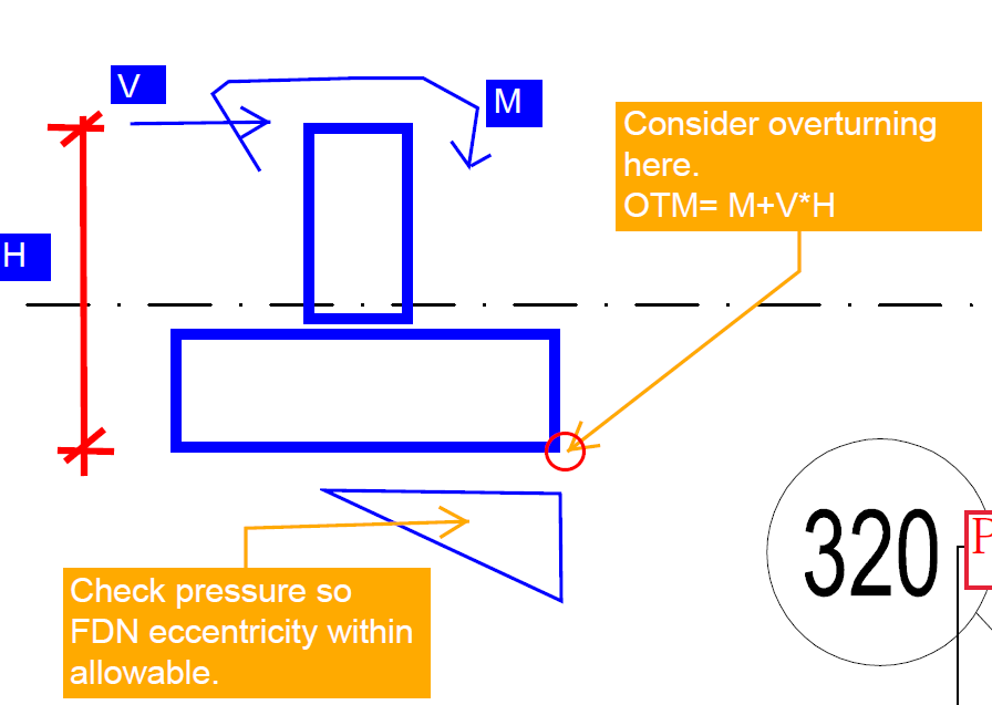
hani, Looks like your pole foundation is a shallow (isolated) foundation resting on grade. First you need to calculate the applied loads at top of pedestal on which your pole is sitting. Then you need to check the foundation size to make sure the overturning and sliding of foundation is within the allowable limits based on the code that you are following. This will include a check in which you will check the compression/ tension couple in foundation and to make sure eccentricity is not large so that you foundation is not in tension. Such checks are provided in standard hand books. For passive pressure, see what your geotech report says. Normal practice is to ignore it. Thanks. -
This is a good point. Snow drift should also be calculated for all structures especially for canopies as they can be lightly framed! Thanks.
-

Post Welded Base Resting on Levelling Nuts
UmarMakhzumi replied to Syed Adnan Aqib's topic in Steel Design
@Simple Structureshas raised some good points. Just to add to it that shims have dual role. One is around levelling and /or filler plate and other is also to provide bearing before grouting is done. I have done some structures where we have used shims to level as well as to provide bearing (before structure installation) under columns and size of the shims was based on concrete bearing limit state using dead and construction wind (1 in 10 years). Thanks. -

Post Welded Base Resting on Levelling Nuts
UmarMakhzumi replied to Syed Adnan Aqib's topic in Steel Design
Saqib, The solution would be to complete the erection asap and grout the base as-is. Load path will be complete once grouting is done. Meanwhile, you can provide shim stacks under column bases to avoid other base plates from bending. This is my opinion. You should contact the design office to get the solution from the Engineer of Record who has stamped the drawing as liability lies with him/her and follow what he/she says. Thanks. -

Retrofit of damaged RC Bridge Piers
UmarMakhzumi replied to Saleem Ahmad Malik's topic in Seismic Design
Saleem, The title of your post saying Damaged Pier. What kind of damage has been observed for the pier. To answer your question, you need to look for literature on Pseudo Dynamic Loading and correlation to member strength and use published correlations to establish basis for your retrofit design. Thanks. -
This kind of connection is very common. What is the weight of the hoist/ trolley that would be running on the lower beam. The following things should be considered. 1) Include impact forces (vertical, longitudinal, and lateral) for design of beam as well as connection. 2) I suggest adding stiffener between the two bolts on each side of girder. 3) Deflection of bottom beam should be limited to L/600 or vendor criteria whichever is more stringent. 4) 12 mm bolts are very small. Generally we don't use less than 19mm (3/4" bolts). Bolts should be ASTM A325 or A490. 5) For hoists, bolts should be pretensioned. This is important. Now, for designing such connection, you need to resolve the force at beam end for different position of hoists, the use the maximum value. You have 4 bolts, so calculate shear and tension for each bolt. Consider prying in your calculation. How to do the calculation is very simple. I don't have an example but you can get it from any text book on connection design. Thanks.
-

Post Welded Base Resting on Levelling Nuts
UmarMakhzumi replied to Syed Adnan Aqib's topic in Steel Design
HI Aqib, Generally, when erecting steel structures bases, shim stacks are used that are placed under the base plate to avoid any base plate bending (as the base plate would directly rest/ sit) on the shim stacks (compressive load) and once the structure with major members and bracing (in-place) is installed, the grout is done. The reason looks very simple that base plate has not been design for erection loads that match erection procedure or the engineer designing assumed the contractor was qualified and would install per industry standard. Keeping the column on levelling nuts is big mistake. Out of curiosity, how long was the structure left like this before the base plate bending was observed. Also, why hasn't this been grouted? Thanks. -
Hello Everyone, Recently I have been busy with some checking work related to Shell structures in SAP2000 and Staad Pro. For plate analysis, I came across a good reference document. It is written for Staad but is very good for understanding of the plate forces and results as the plate force convention is almost same in all softwares (Designed for unit width, forces based on local coordinate system, and moment are in the direction of local axis). I can't remember where did I get this document as it was a direct download while exploring google. It is attached. Thank you. Plate Analysis Results and Design Forces in Computer Program.pdf
-
Yes, you can use a custom load combination to scale the results or export the results to Excel and do the custom scaling. Thanks.
-
That is strange. You can try a lower value like 0.001. If you remove the wall, you can model dummy columns to replace the shear wall. The connection of beam can stay as it is. Thanks.
-
I think stiffness modifiers dont apply to local checks, so you can consider the full moment of inertia. The intent is more for global analysis, I believe (not 100% on this). Having said that there were recent conversations on the forum on stiffness modifiers. I would suggest that you search the forum as well. Thanks.
-

Design of shear walls for Moment Envelop?
UmarMakhzumi replied to abbaskhan2294's topic in Seismic Design
Like Baz said, envelopes would summarize the max, but they may lead to very conservative design. CSI itself suggests not using envelopes. Ref: https://wiki.csiamerica.com/display/etabs/Envelope+combination+not+for+design -

Structural Steel TS/YS Ratio
UmarMakhzumi replied to Muhammad Nakhshab Ajaz's topic in General Discussion
You can check these values against recommendation in ACI. The following excerpt is from ACI 318-08. From the commentary: I hope this answers your question. Thanks. -
I think the limitations is for beams on L/d is for beams to be designed per “beam theory” which means that plane sections remain plane before and after bending. This assumption is not valid for deep beams or beams that violate the L/D ratio stated above. You can still design those beams using strut and tie method. It is explained in ACI. Thanks.
-
For Sliding, you can consider friction between footing base and soil. Friction coefficient is normally 0.5 but varies from code to code. Thanks.
- 4 replies
-
- sliding
- overturning
-
(and 1 more)
Tagged with:
-

Pure Torsional Mode as 1st Mode in Tall Building
UmarMakhzumi replied to Howard Roark's topic in General Discussion
I don’t have experience with time histories for seismic. I have a done a few for rotating equipment so I won’t be able to recommend you anything. Thanks. -

Zero Concrete Shear Strength in ETABs
UmarMakhzumi replied to Osama Anwar's topic in Software Issues
3” spacing is very normal for ties/ stirrups. -

Zero Concrete Shear Strength in ETABs
UmarMakhzumi replied to Osama Anwar's topic in Software Issues
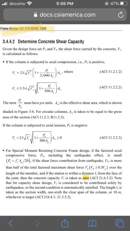
Please see snapshot and the link: https://docs.csiamerica.com/manuals/etabs/Concrete Frame Design/CFD-ACI-318-08.pdf -

Pure Torsional Mode as 1st Mode in Tall Building
UmarMakhzumi replied to Howard Roark's topic in General Discussion
This is the solution. Try to convince your architect. You never want your first mode to be in torsion even if it is within the allowable limit. -
That is correct. You just model slab to column like normally you would model. Analyse your ETABS model, get maximum shear and moment for the worst cases that would be max tension and max shear. Now you have to provide a mechanism to transfer that moment and shear from the slab to the column. Which you can do by using weldable rebars. Provide an end plate to column. See the sketch. Sizes where shown are just for example as I have no idea what your loads are. **Update** I also edited my sketch to show concrete breakout that you will need to check per ACI Code. It is also a good idea to provide shear ties for that, but you will need to develop Ldh for ties too. Also added circle on weld symbol to show all around welding. The break out line is show incorrect, as it should start from reinforcing bar,not end of plate. Sorry but hand markups using mouse are tough.
-
Short answer is NO!
-

Load Combinations for Water Tight Structure
UmarMakhzumi replied to Muhammad Shaihan Ayub's topic in Concrete Design
Please refer to ACI COMMITE REPORT 224. Thanks. -
Part of the reason the forum went quiet as I found out recently was our Anti-Spam system. Almost all new users that registered on the website are now tagged for manual approval by Admins. Since that takes some time, therefore, the new users don’t get approved right away and by the time they get approved, the question for which they wanted to come to the forum is probably solved. We are looking into it. Apart from that, this forum focuses on a very small subset of Civil Engineering professionals - we also do admit that participation level is low as target audience is very limited and there are some challenges that we need to overcome. Thanks.
-
You should at-least try the suggested solution. It will fix your model. There are other good points raised by other members that you can consider as well. If the load on balcony is not much(not sure as I see a masonry facade in the picture) you can also try designing it as a cantilever slab. Thanks.


