-
Posts
1470 -
Joined
-
Last visited
-
Days Won
446
Content Type
Profiles
Forums
Events
Everything posted by UmarMakhzumi
-

Moment Capacity of retrofitted section
UmarMakhzumi replied to Fatima Khalid's topic in Concrete Design
Fatima, What has been stated above by Baz is very useful and you can use it for composite sections of any given configuration. Generally speaking, strength contributions by steel angles are very low and wouldn't add much to a concrete column section. I have used angles at corner of concrete section to allow welding of lighter items (like small pipes or cable trays) or to protect the corner from deterioration. I would suggest to ignore angles and don't rely on them. Now lets say you still want to consider the angles, for that case follow what Baz has said. So you can model a composite section or manually calculate the moment of inertia of combined section. By doing that, you can run analysis model and get your moments in the composite member due to the applied loads. Additional checks to do would be to make sure the bolts connecting the angles to the concrete don't fail before your angle attains yield strength. You can calculate the force in the bolts by using the Shear flow formula VQ/I. You will need to check different sections along the length as moment is changing constantly along the length. I hope this helps. Thanks. -
Your applied loads need to match actual situation. I am not sure what is happening there, but if you have a simple residentail balcony, you can't have a 840kN shear due to area load (assuming regular areas). Did you just model the balcony by itself and compared it against hand calcs for shear? If not, please do so.
-

Bearing check for Circular Hollow Sections CHS members
UmarMakhzumi replied to WR1's topic in Steel Design
See AISC Design Guide 24: Hollow Structural Steel Connections. Thanks. -
You need to check your applied load. Is this correct to say that cantilever beam is a balcony beam? If yes, the only load on the beam is the tributary balcony area that it is supporting and that can’t be 830kN. Check your area load units, material assignments, section properties. Clearly there is something wrong in the model. Another method would be to check which load combination is governing shear, then run individual basic load case in that load combination to trace error. Thanks.
-
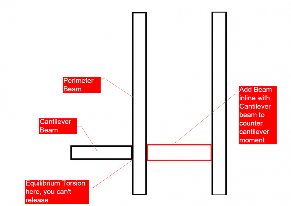
There has been very good discussion on this, I will just add my 2 cents. I don't have ETABS, so I have no idea about what the framing so the following comment *might* not be applicable if framing is not what I am thinking, however, please note that for beams supporting cantilevers, you shouldn't release the torsional moment or change its modifiers as the torsion would be equilibrium torsion not compatibility torsion. If your beam is failing, just add another beam inline with cantilever. See image below. Also, I would suggest to *please* add images to question rather than ETABS model as not everyone has the software to check. Also checking someone else's file is cumbersome and time consuming, which a lot of people who volunteer here might not find time for as a result of that the thread may stay unresponsive. Thanks.
-

Crack Width For Watertight Requirements According To ACI
UmarMakhzumi replied to WR1's topic in Concrete Design
I think its is more prudent to follow this recommendation for members subject to direct tension forces. For rectangular water tanks, forces on wall are flexural and the complete section is not subjected to tension. These are my 2cents. -

Crack Width For Watertight Requirements According To ACI
UmarMakhzumi replied to WR1's topic in Concrete Design
@Rana, I am working on a structure where I have to use this. I have provided my conclusions here: I couldn't find the reference that you have discussed about limiting stress in reinforcement to 0.33*fy based on ACI 350-06. May be I am missing something. Have a look and let me know when you get some time. Thanks. -

Minimum Reinfocement Criteria For Crack Control
UmarMakhzumi replied to abdulqadeer29's topic in Concrete Design
So looks like today, I came across the same problem that is being discussed here. I had to provide a design criteria for a buried concrete pit. I will summarize my findings below for the benefit of everyone. This applies to structural members that are subjected to environmental exposure conditions or that are required to be liquid tight. 1) The first step is to calculate flexural demand in the walls of concrete pit/ water tank based on all possible conditions. For the case of buried concrete pit, it included, empty condition (no fluid in the pit) , operating condition (full of liquid), test condition (no backfill around the pit and it is full of liquid) etc. Buoyancy checks should also be performed. 2) Compare required flexural reinforcement against minimum reinforcement ratio = 0.006 per ACI 350, Table 7.12.2.1 & ACI 224 , Section 3.5 and provide whichever is the maximum. The ratios provided are basically temperature and shrinkage reinforcement ratios based on gross section so provide half of the reinforcement at each face. 3) Satisfy maximum crack width of water-retaining structure = 0.10 mm, ACI 224R-01 Table 4.1 based on the reinforcement already provided. If the reinforcement is inadequate, increase the reinforcement till this requirement is met. To meet this requirement, smaller bars should be used with close spacing. Now a few comments on the the excellent discussion above. @Khawaja Talha post above is applicable for all normal cases where there is a restraint to shrinkage and temperature movements only. If you have a condition like that, you need to provide 0.45% reinforcement ratio in your slabs. Example of a situation where this would be applicable will be a structure where movement or expansion joints haven't been provided at industry standard spacing. But if you want to meet liquid tight start with 0.6% as a minimum and work your way as suggested above. Other posts above explain the same things in a slightly different manner but all good. Thank you- 12 replies
-
- minimum reinforcement
- water tight structures
-
(and 1 more)
Tagged with:
-

Global torsional instability issue in the building
UmarMakhzumi replied to abbaskhan2294's topic in Seismic Design
There is another reason for which I was suggesting additional walls. You have a single moment frame in transverse direction for each bay. That is not a good practise as system has no redundancy. I would suggest that you reconsider your framing or design it using over-strength factors as system is not redundant. Thanks. -

Global torsional instability issue in the building
UmarMakhzumi replied to abbaskhan2294's topic in Seismic Design
Abbas, I would suggest the following: 1) Add additional shear walls as marked. 2) Add spandrels Thanks. -
Mumtaz, You need to select a referecne steel book and solve examples to get some idea. Salmon and Johnson is good but it can be intimidating for new people as it has complex problems. I use Kulak and Grondin but its more for Canadian Codes. What steel code do you intend to follow. Thanks.
-
Based on the thickness of tie beam, between two pile caps, it would react differently to externally applied loads. For cases where your tie-beam is deep, it would provide significant restraint to any movement at pile caps end (it will act as a moment and shear restraint), and where it is not, it won't (only axial restraint) so reinforcement would be different for different depths as stiffness is different. You can reduce the size of tie-beam, and check the response. A reduced depth tie beam would mean more reinforcement in pile cap and vice versa. There are trade offs in pile cap or tie-beam reinforcement depending upon the thickness of the beam and you will have to pick the one that suits you. Thanks.
-

Modelling of Nicholson's Obelisk in SAP2000
UmarMakhzumi replied to Howard Roark's topic in Software Issues
This is no different than a shearwall. You can view the tutorial below to see how you model walls in ETABS. It depends but Sap2000 and ETABS are equipped with some great tools that other softwares lack. You can but try to model a rectangular one first. The meshing will get tricky with tapering and your model will generate a lot of errors (although tapering is not that difficult to do) but stick with rectangular one for simplicity as you are new to this. Well, if you want to do a fancy accurate looking model, I would recommend using solid elements. The image shows that you are using shell elements and with those elements, modelling layers is fairly tricky. As a starting point, just model a single base. Ignore the tapers and model straight walls, get your results and keep it simple. Hope that helps. Thanks. -
This might help. Regards
-
https://www.amazon.com/Fooled-Randomness-Hidden-Markets-Incerto/dp/0812975219
-
I think there is a lateral force resisting system option that involves non-orthogonal arrangement. Look it up, I don't know the exact name. You should be using that. Regards,
-
Yes, it is very normal for different directions to have different systems and different time periods. Thanks.
-
Welcome aboard.
-

Truss Structure is unstable or Ill-Conditioned
UmarMakhzumi replied to kamruzzaman shohagh's topic in Software Issues
I don't have ETABs but with trusses, you should make sure your top and bottom chord segments are modeled as continuous members. The ends can be released. That is the most common mistake that I have come across. -

How to get reaction of shear wall in ETABS..?
UmarMakhzumi replied to siju simon's topic in Concrete Design
Hi Siju, Please see the following: Thanks. -
I guess so.
-
These are all good questions. Since there is no standardization in Pakistan, the best thing to do would be to determine it on a case to case basis. For example, if you need to provide an estimate, go checkout a local construction site where block masonry is being done, and measure quantities for small sample. Then use the ratios for your project and state listing your assumptions. I am not aware of how this is addressed in Pakistan. If someone has estimation experience relevant to the posted question, please feel free to comment. Cheers!
-
Hi Rifat, Generally your course books should suffice for that purpose. Are you looking for country specific books? Thanks.
-
Hi Usman, We are very pleased to have you here. Welcome aboard. Thanks.


