-
Posts
50 -
Joined
-
Last visited
-
Days Won
5
kHURRAM ALI last won the day on July 27 2020
kHURRAM ALI had the most liked content!
Profile Information
-
Gender
Male
-
Location
karachi pakistan
-
University
NED universisty
-
Employer
structure engineer in BEG associates
-
Interests
civil engineering
Recent Profile Visitors
3,281 profile views
kHURRAM ALI's Achievements
-
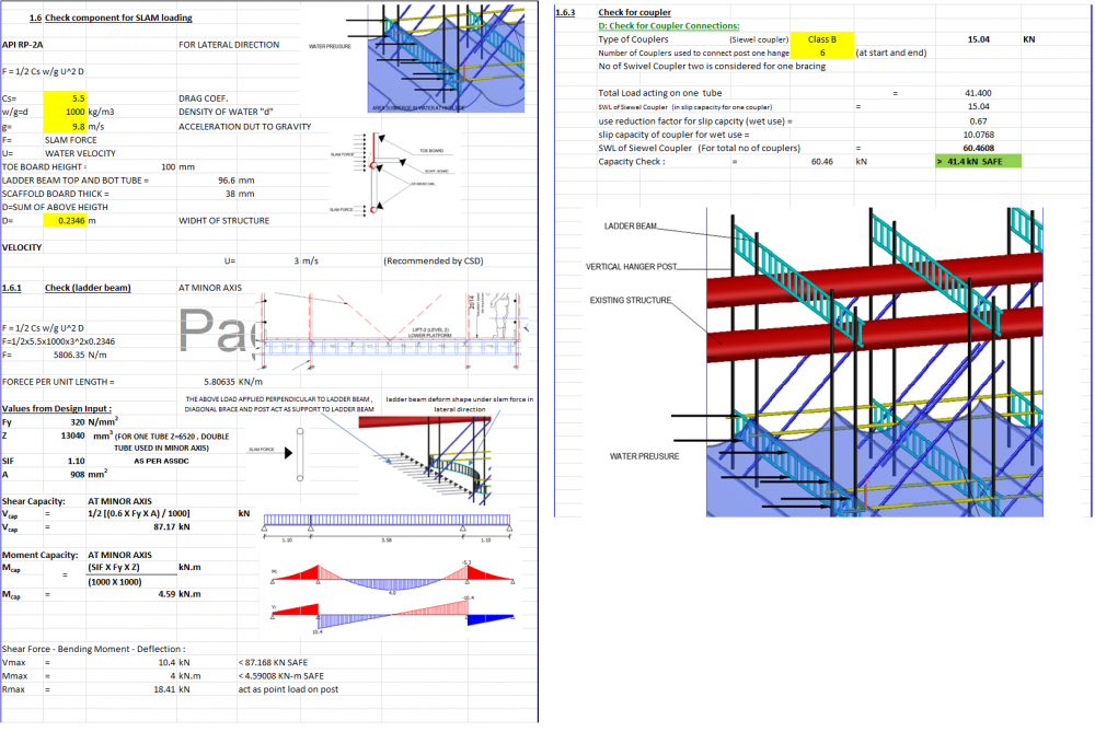
one of our clients required scaffolding for Boat landing for an offshore platform, I have submitted the design in a normal manner, like designing it for medium duty (2.4 KN/m2) , but the client engineer wants to check it for seawater slam forces and check coupler capacity if its get wet. During high tied Scaffolding may submerge in water, not completely, but partially, Does anybody guide how scaffolding design if it's submerged in water? When scaffolding is submerged in water couplers get wet, which reduces friction between the tube and coupler, so how much will it reduce, is there any test from which we can find its capacity? no person will work during high tied obviously, but our concern is that scaffolding should bear wave forces so that it can be used after tied gets low i did some calculations for slam forces, appreciate if someone review and give valuable feedback specially on coupler capacity thank you
-
 Nawaz Qasim reacted to a post in a topic:
Beam Fail In Torsion And Shear In Etabs Then Why Torsion Modifier Reduce To 0.001
-
 Waqar Saleem reacted to a post in a topic:
Beam Fail In Torsion And Shear In Etabs Then Why Torsion Modifier Reduce To 0.001
-
Muhammad Khalid started following kHURRAM ALI
-
 Muhammad SAqib shah reacted to a post in a topic:
Reading the drawings in SAFE
-

Reading the drawings in SAFE
kHURRAM ALI replied to Tyrion.Lannister's topic in Spreadsheets & Softwares
i think BC means bottom contineous , BE means bottom extra , similarly TC and TE means top contineous and top extra -
what modifiers are you taken , 0.7 (uncracked) or 0.35 (cracked) , you have to check first your shear wall stresse with rupture stress fr=7.5(f'c) in psi , if wall stresses exceeds from fr than you have to take wall as a cracked section i.e 0.35 modifier otherewise 0.7 is o.k , as per ubc code. when wall modifiers changes from 0.7 to 0.35 , make wall to attracts lesser forces , by which its starts to pass in shear , but it depends on how much force is taken by shear wall
-
 UmarMakhzumi reacted to a post in a topic:
Max Percentage of steel in Columns
-
 Osama Anwar reacted to a post in a topic:
Max Percentage of steel in Columns
-
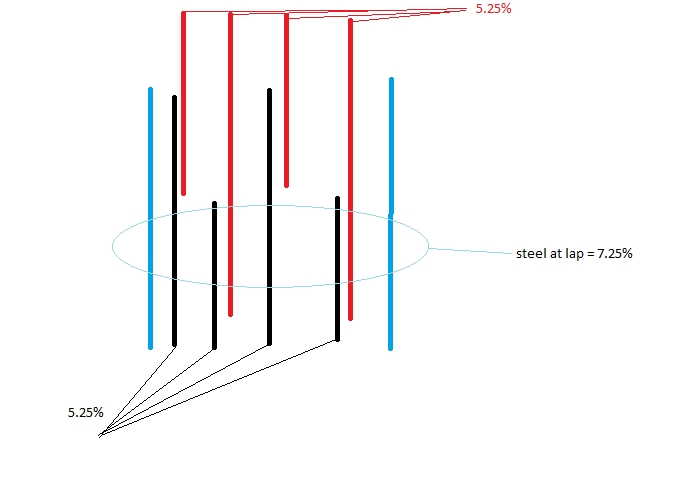
use staggered bar detailing at lap joint , by doing this , you can provide 5.25% steel in column instead of 4%, at lap joint column steel from above story will be half , so total steel at lap will be 5.25+5.25/2= 7.875% , which is less than 8% for IMRF . This detailed not applied to SMRF , as code restricted max column steel < 6%
-
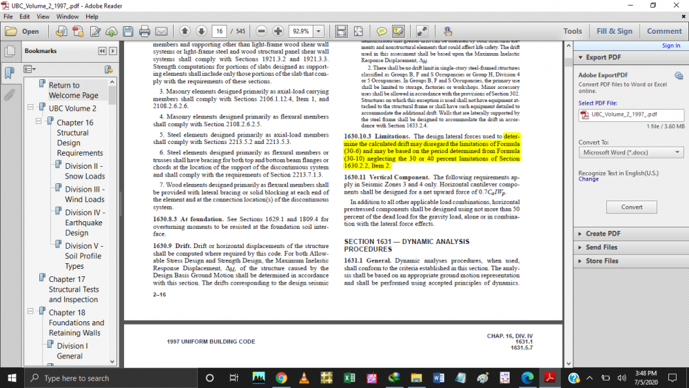
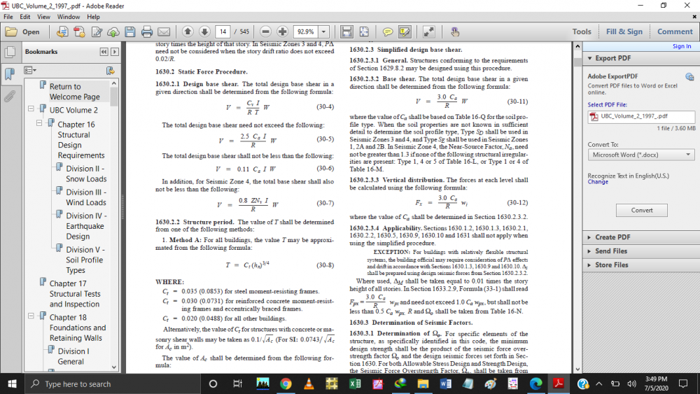
Aslamwalekum to all, Building base shear as per UBC is calculated from equation 30-4 to 30-7 as shown in first image , but for drift it allows to ignore eq 30-6 as shown in 2nd image and calculate base shear on time period of Method B eq (.30-10) . My question is if model a building in ETABS , It calculate base shear from equation 30-4 to 30-7 , so how can i make ETABS to ignore eq (30-6) for drift calculaton only.
-
 Ayesha reacted to a post in a topic:
Etabs model dont show auto seismic calculation in summary report
-
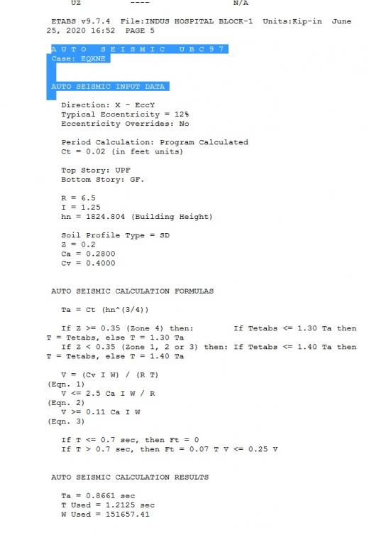
Aslamwalekum to all, I want to check my building base shear , ETABS give its calculation in summary report which is shown in attached image but, in few models it dont show these calculation , can somebody review it and suggest what is the problem in my model. the ETABS model and its summary report is attached with it BEHRIA TOWN-ETABS-9-10-2019-REV-47-PART-1.final.e2k LOADING.txt BEHRIA TOWN-ETABS-9-10-2019-REV-47-PART-1.final.e2k LOADING.rar
-
 UmarMakhzumi reacted to a post in a topic:
special seismic option in ETABS 2016 ????
-
 Rifat reacted to a post in a topic:
Etabs Torsion & Longitudinal Rebar Output
-
As per our office practice, we add shear r/f with torsion , for flexure we divide torsion r/f by 2 , then add this r/f in top and bott longitudinal r/f
-
 UmarMakhzumi reacted to a post in a topic:
Frame Release clarification
-
its now in the preference override option
-
if you want to model a beam as simply supported beam , then you will need to end realese , so the beding moment draw as for simply supported beam, other wise without relase , depending upon the stiffness , negative and positive both moments comes in beam
-

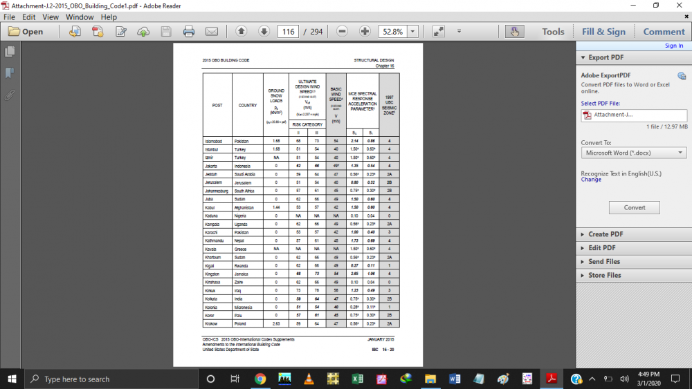
IBC code use instead of UBC 1997 in karachi
kHURRAM ALI replied to kHURRAM ALI's topic in Seismic Design
you can download from below link https://de.usembassy.gov/wp-content/uploads/sites/21/2016/08/Attachment-J.2-2015_OBO_Building_Code1.pdf -

IBC code use instead of UBC 1997 in karachi
kHURRAM ALI replied to kHURRAM ALI's topic in Seismic Design
-
 Saifuddin18 reacted to a post in a topic:
Eqution for calculating bearing capacity
-

Eqution for calculating bearing capacity
kHURRAM ALI replied to muneeb1213's topic in Foundation Design
commonly raft have bearing capacity on 2in settelement , while isolated footing have bearing capacity on 1 in settlelemt, so diifinitely bearing capacity at 2in settlement would be greater than bearing capacity at 1inch settlement- 3 replies
-
- bearing capacity
- foundation
-
(and 1 more)
Tagged with:


.thumb.jpg.51aee45d64f270ded062428cf8d8117e.jpg)


