EngrUzair
-
Posts
475 -
Joined
-
Last visited
-
Days Won
242
Content Type
Profiles
Forums
Events
Everything posted by EngrUzair
-
The file referred in the link is Chapter 4 of 2002 version (ASCE 7-02) of 'Minimum Design Loads for Buildings and Other Structures', dealing with Live Loads. Reduction of Live Load is permitted, as per procedure & limitations described in Section 4.8 of this chapter. This information is also available in later versions of ASCE 7. In case of ASCE 7-05, it is provided in Section 4.8, whereas in ASCE 7-10, you may find it in Section 4.7 of the standard. Regards.
-

IS PAKISTAN PREPARED ENOUGH TO HANDLE THE NEXT "BIG ONE"??
EngrUzair replied to Fawad Najam's topic in Shout Box
Very informative & impressive article, on a very very important topic of earthquake awareness, both technically as well as for the general knowledge of common people. And, that too in Urdu language for easy understanding of even non-technical people. Fully appreciated. Except a mistake (most probably typographic) of indicating Quetta in Zone 3 (Instead of Zone 4), the article is really superb, both from technical information as well from clarity points of view. Hopefully, it would help the readers understand how the earthquakes initiate, what are their negative effects & why their homes should be earthquake resistant. Regards. -
To the point background & design examples prividing step-by-step procedure for the design of combined footings, including determination of thickness, is available at the following link. Design calculations are based on ACI 318-05 requirements. Combined footings Regards.
-
WA. Spacing of ties for RC columns located in earthquake zone 3 & 4 is governed by Section 21.4.4.2 of ACI 318-05, and other related sections. You may check the required minimum & maximum tie spacing yourself, using the structural information (columns dimensions and bar diameters) for the columns used in the building under consideration. Regards.
-
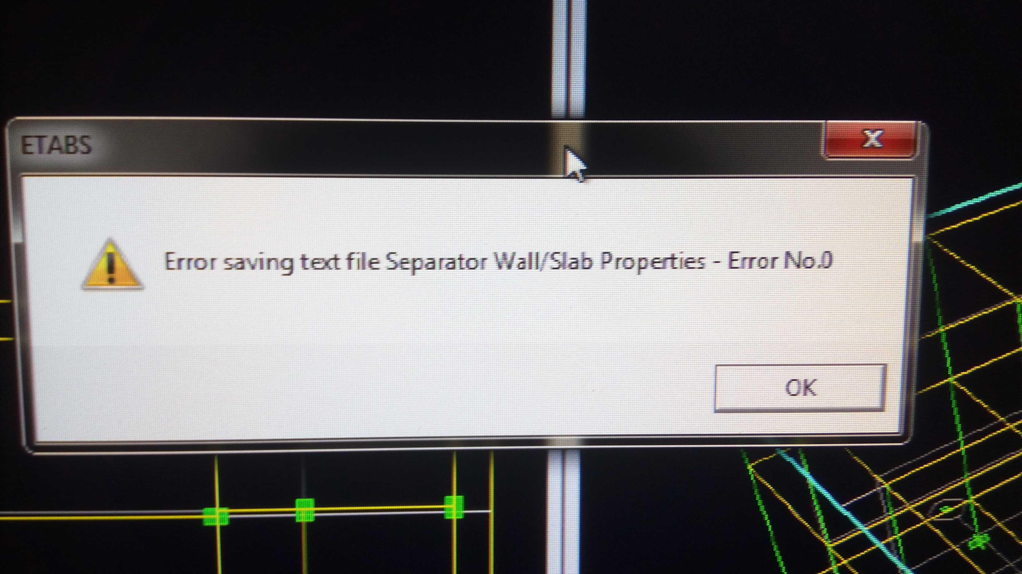
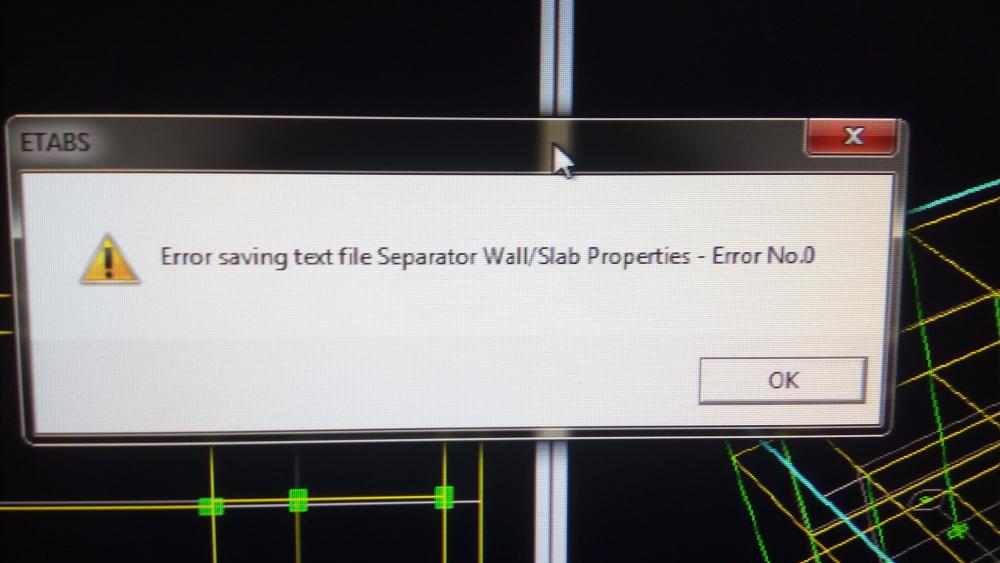
Dear colleagues, AA. I am analysing a 2-storey RC frame structure in ETABS version 9. Geometry of the building was first modelled in Autodesk Revit 2017, and then transferred to ETABS using Revit to ETABS exchange file. The model was updated in ETABS 9. However, on trying to save the file, every time following error was encountered. "Error saving text file Separator Wall/Slab Properties-Error 0" (See the attached image.) The model was however being saved, alongwith displaying above-mentioned error message. In the end, when I tried to run the structural model, the program did not run analysis & stopped, after displaying the following message:- "Unable to complete operation 'Run Analysis'!" Keeping in view above situation, here are my questions: a. What may be the source or reason of this error? b. How this error can be rectified using ETABS 9? Regards.
-
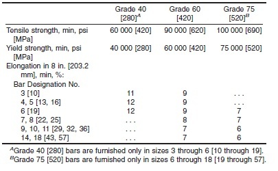
ASTM A615 requirements are given in the attached image.
-
Elongation Limits are given in the material specifications applicable to the reinforcing bars under consideration. For example, in case of American Codes, these limits are available in relevant ASTM standards (e.g., ASTM A706, ASTM A615 etc.), depending upon which of these specifications correspond the rebars being used. In case of eurocodes, elongation limits should be available in respective eurocode or British Standard (BS 4449 etc), as applicable. Regards.
-
Difference between Etabs 9.6 vs Etabs2015
EngrUzair replied to Alhamdu Abdella's topic in Concrete Design
Many major changes & enhancements have been made in ETABS between versions 9.6 and 2015. Details of these enhancements are given in following links:- 1. ETABS 2013 Release Notes v1300.pdf 2. Latest etabs release notes Regards -
Following article (particularly its first paragraph) may help you understand the role of column ties in resisting shear during an earthquake:- EQ Tip 19.pdf Regards.
-
Check the following link for the required information:- https://wiki.csiamerica.com/display/safe/Import+response-spectrum+load+case+from+ETABS+into+SAFE Regards.
-
I would like to add the following comments to what has been said earlier: 1. The document referred by @BAZ, is available at following link:- AISC-Bracing for stability 2. Additionally, the following research report (especially its chapter 6 & Appendix B ) provides useful information on undrstanding & design of bracing:- Bracing Requirements for Elastic Steel Beams HTH Regards.
-
Following link that provides reference to several good documents related to pile cap design (including design examples), might be helpful in this regard:- Pile cap design
-
Base isolated structures (rubber isolators)
EngrUzair replied to Sohaib Iqbal's topic in Students Zone
Do a little search on Google, & you will find a lot of information on Base Isolators. For example, check the following link:- Rubber-based Base Isolators Regards. -
Detailed information on Theory, Design & Installation of hilti anchors is available at the following web link:- https://www.hilti.com/content/hilti/W1/US/en/engineering/design-centers/rebar.html Reference guide & software may also be downloaded from this website. Regards
-
See the reply at the following link:- http://www.sepakistan.com/topic/2441-elcentro-1940-response-spectrum/ Regards.
-
Check the following link:- http://www.vibrationdata.com/elcentro.htm Regards.
-
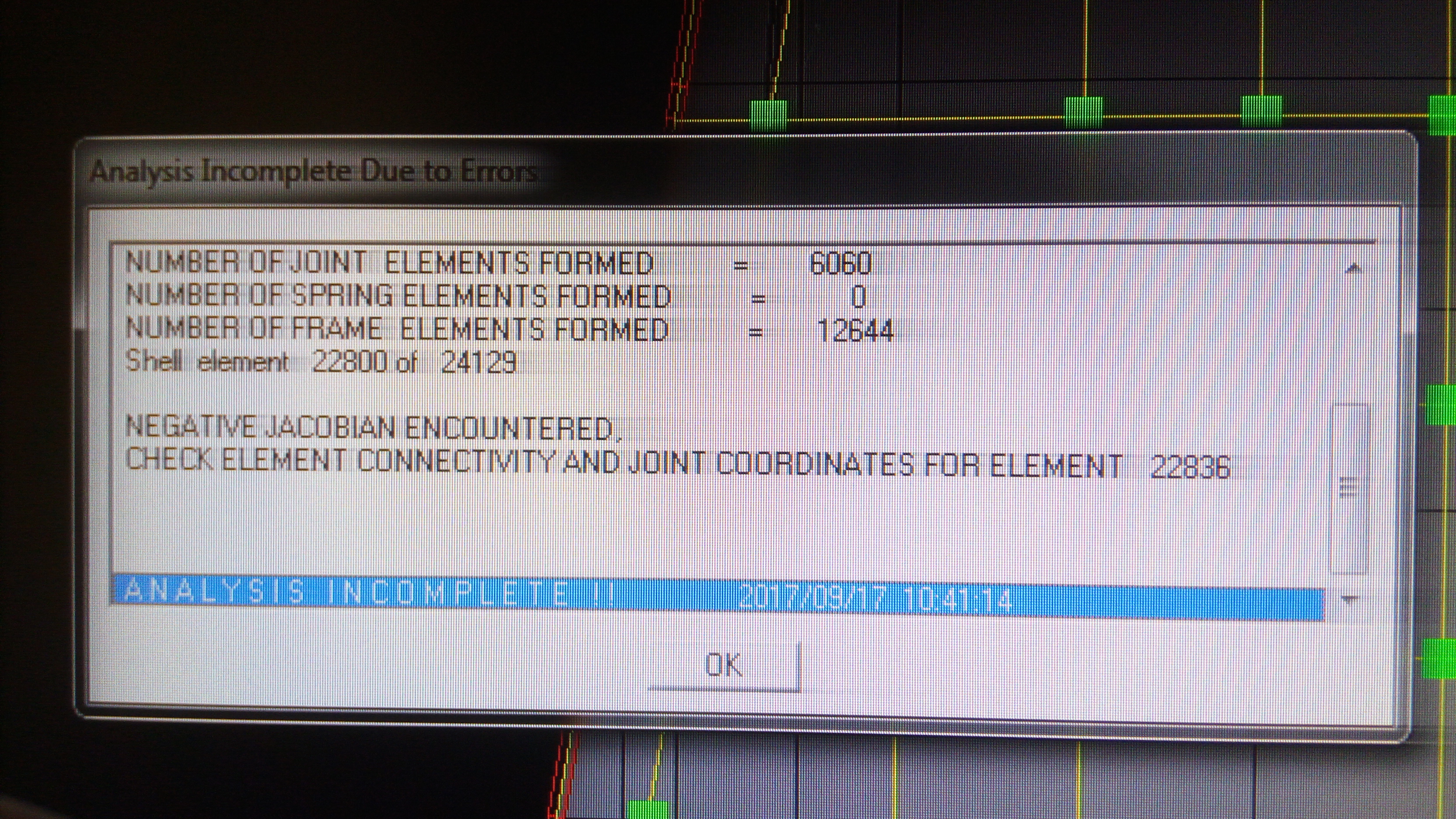
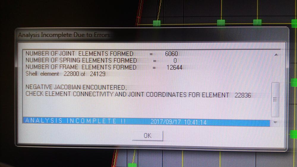
AA. Here is the progress & update regarding the problem described in my original post, for the benefit of the interested SEFP users. 1. Automeshing was adopted in the original ETABS 9 model, with a maximum mesh size of 3 ft for the slabs & walls. The slabs included a raft slab as well, for tranferring the reactions to SAFE. 2. The model was being updated in steps, by refining the geometry along various edges of the slabs according to architectural plans at different floors. Model was running fine at all the steps. 3. The problem most probably occurred when the whole model (including the raft slab) was selected through 'Select all' command & automeshed again as stated in para-1 above. This action meshed the raft slab as well.The meshing of raft slab was haphazard in some regions, because of orientation of slab outer edges in different directions. 4. Following steps were taken in order to sort out the error:- a. Trials were made by automeshing the model at two different maximum mesh sizes of 4 ft & 2 ft (one at a time), but without any positive result. b. Third trial was made using 'default' meshing option ( meshing at grids & in Automesh options, by keeping the 'Further subdivide shell/wall in maximum element size of' option UNCHECKED. This trial helped in running the analysis completely, with 2 Warning Messages indicating presence of unconnected point & frame objects at the specified locations. Deletion of these extra objects removed the warning messages. c. Another trial indicated that thr problem is with the meshing of slabs, and not the walls. d. Trying to locate affected element # 22836 through the procedure advised by Rana, indicated that the relevant output table designates the slab & wall elements by the number types F### for slab elements & W### for wall elements. It followed that element numbers (like 22836 etc) are generated during analysis only. The same facts have been stated above by Saad Pervez. Thus, the affected element could not be traced once again. e. Keeping in view suggestion made by EngrJunaid, the affected model was opened in ETABS 2016. This time the affected element was located & found to be present in the automeshed Raft Slab, provided at the base level merely for exporting the Base Reactions to SAFE for further processing there. 5. Replacing the affected Automeshed Raft Slab, with a new unmeshed raft slab & remeshing the floor slabs & rc walls (after selecting the floor slabs & walls separately) at desired maximum mesh size finally solved the problem. In the end, thanks to all (especially @EngrJunaid) for contribution to reach the solution of subject problem, by suggesting various courses of action. Regards.
-
No. You must not refer to or send results obtained using 'cracked' software for advice. It is illegal. Your queries, and attached information or results MUST be those obtained using Licensed software only. You would need to include details of purchased License, while referring the case to CSI for clarification. Regards.
-
Since you are using Licenced software, the best option would be to refer the case to CSI directly with all relevant details. Regards.
-
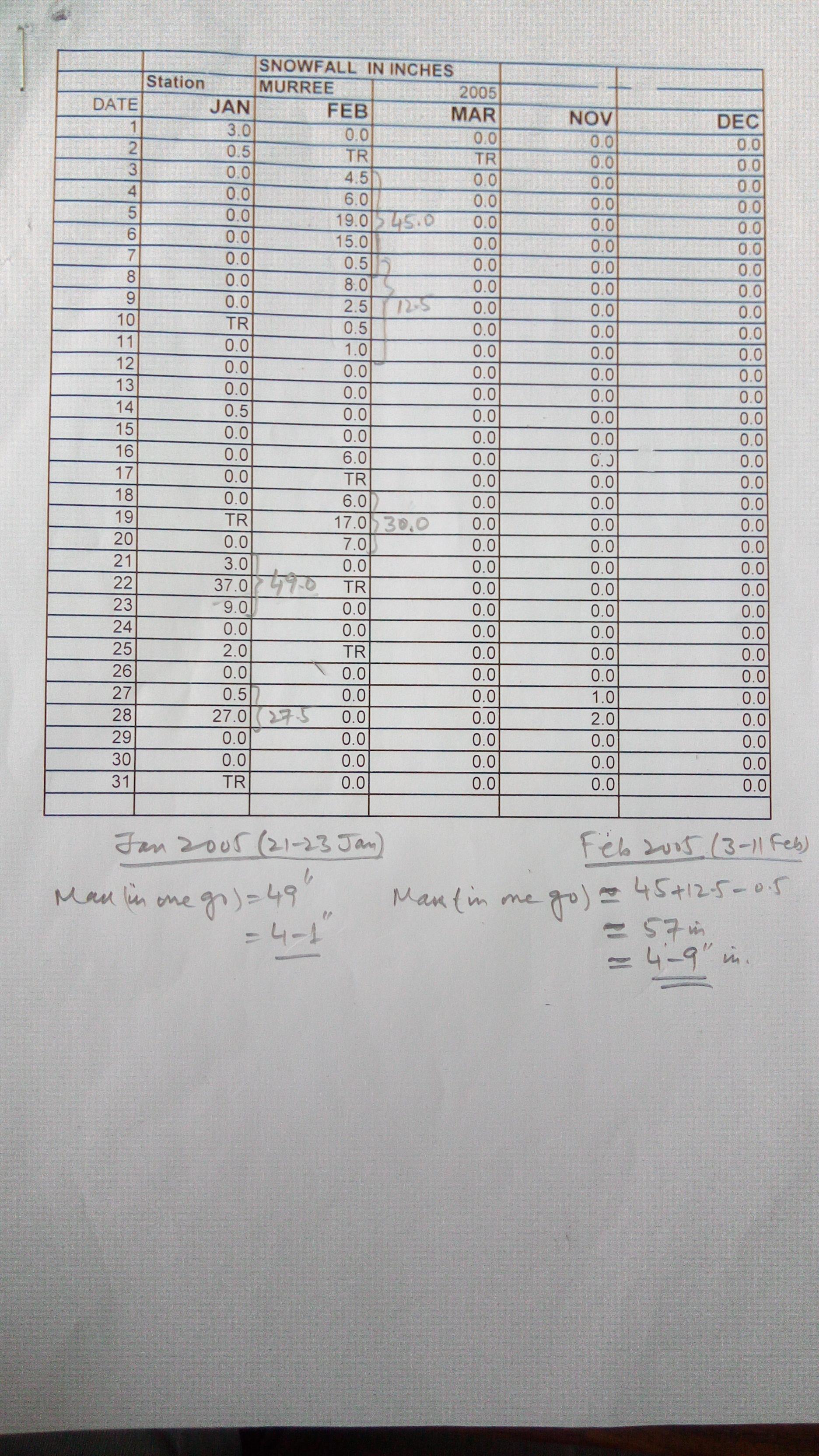
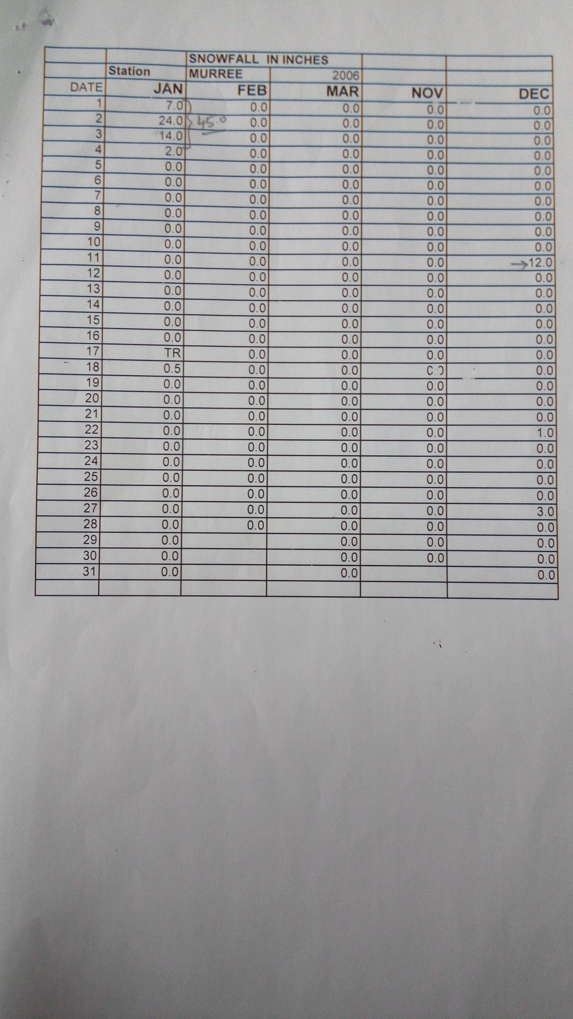
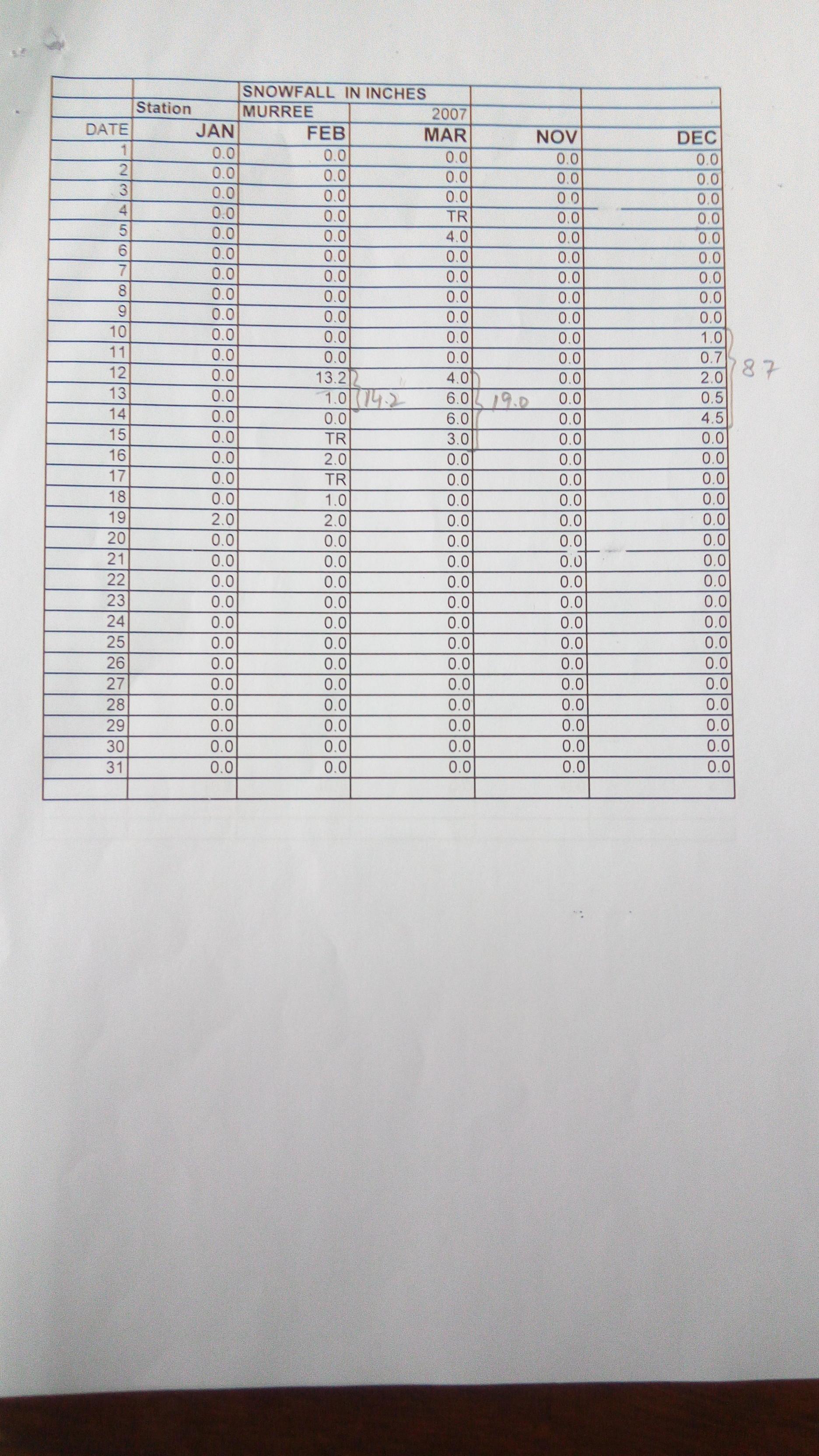
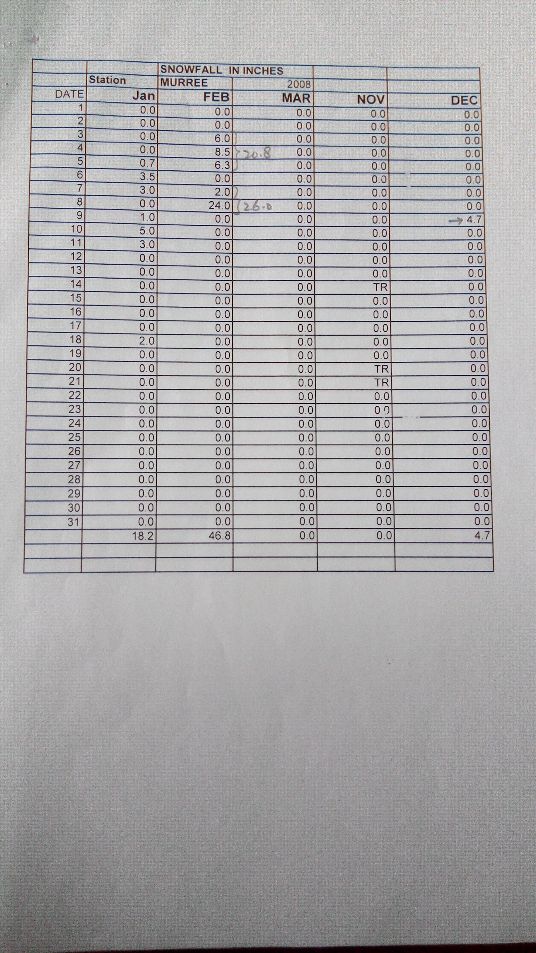
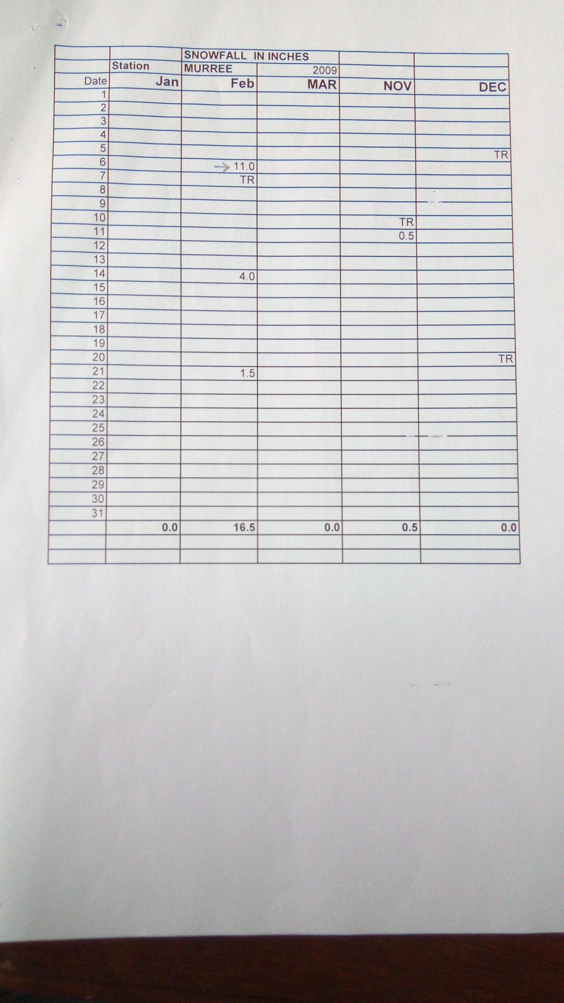
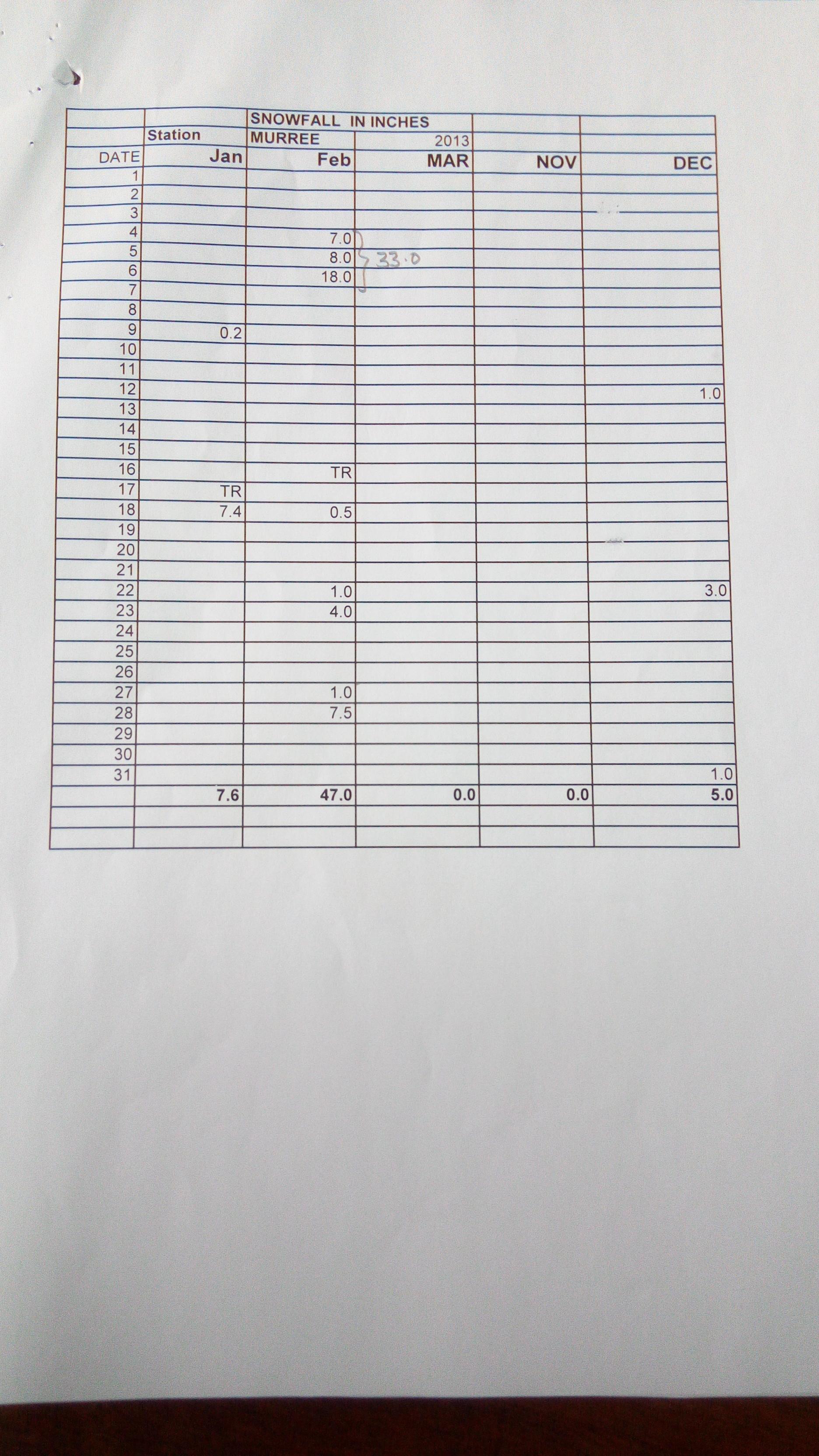
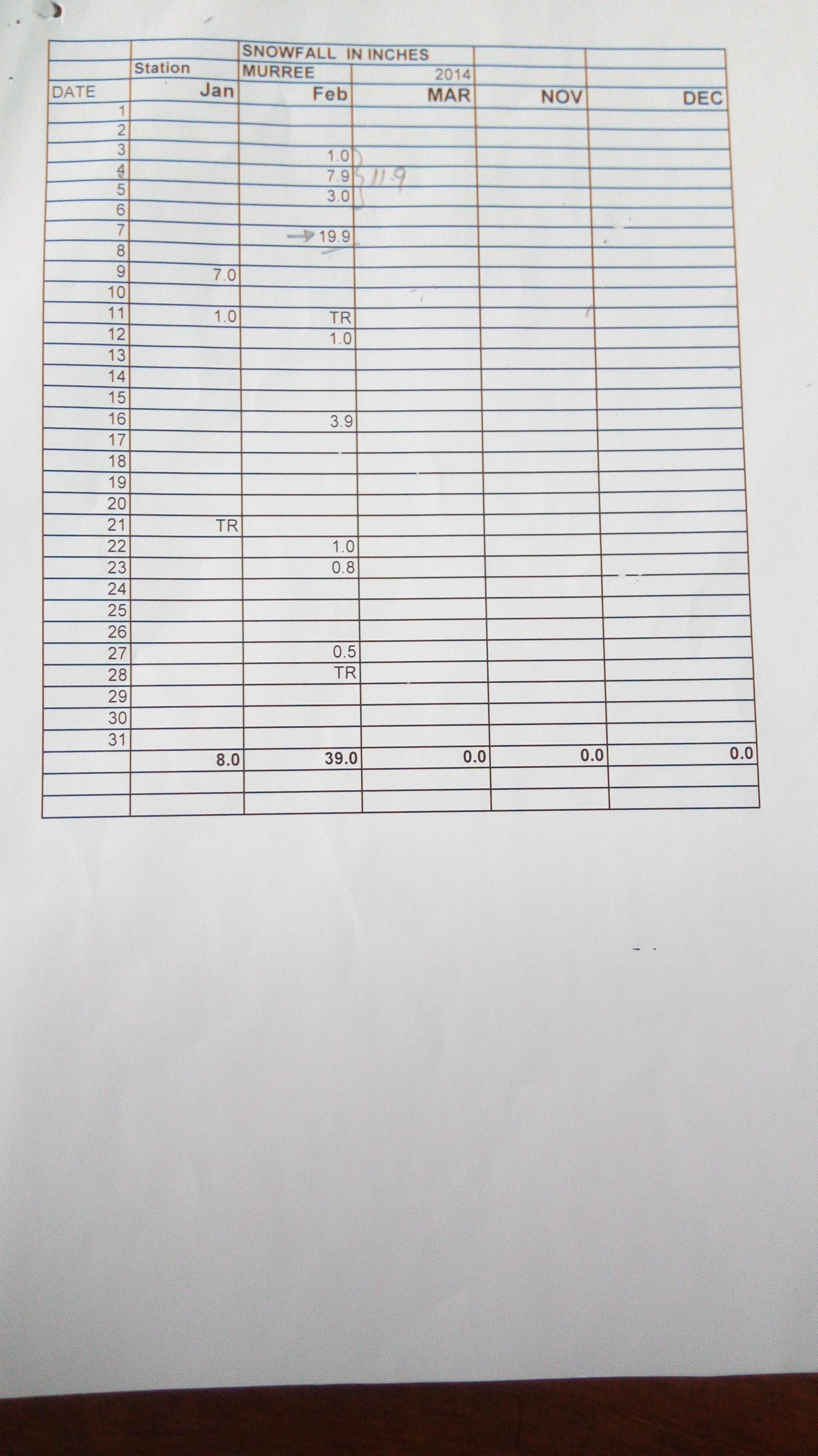
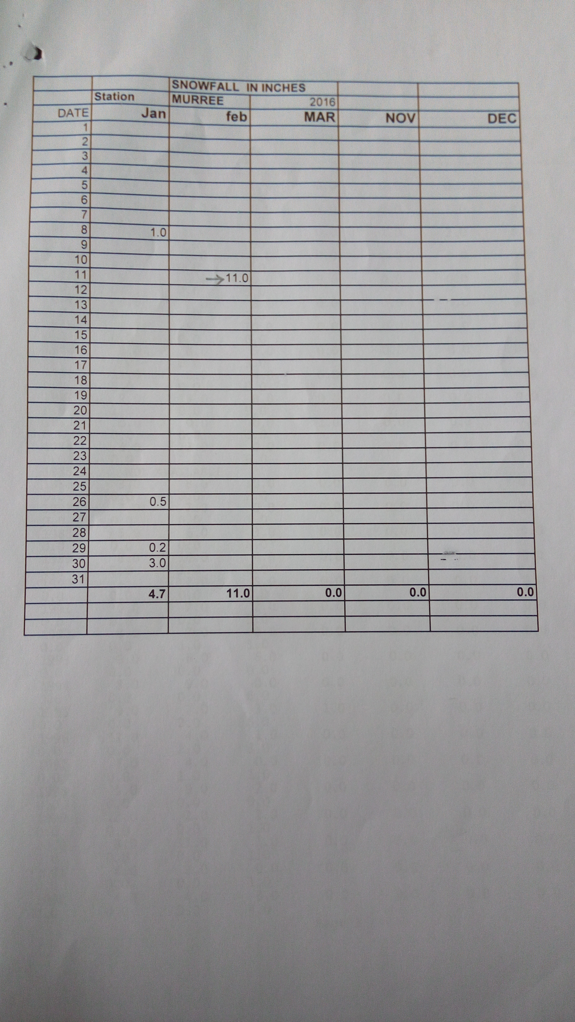
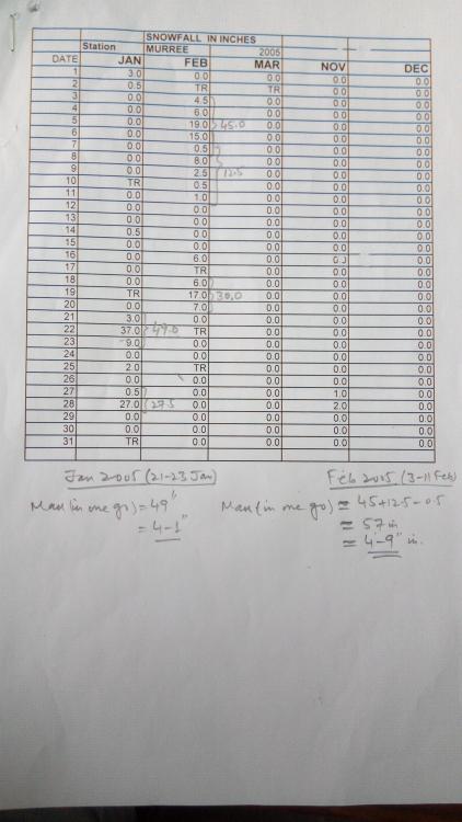
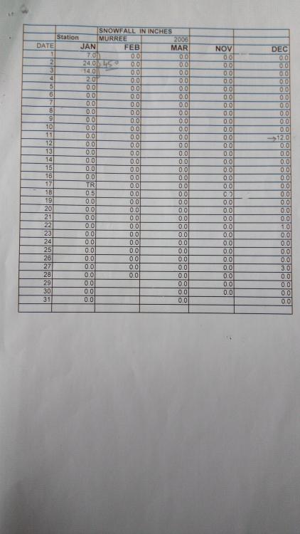
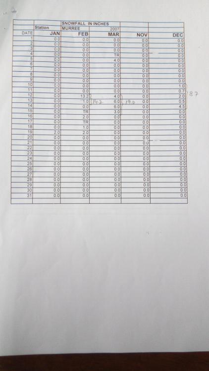
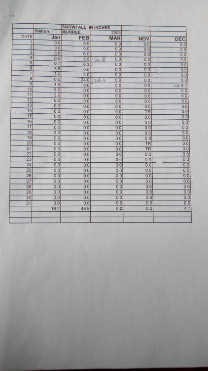
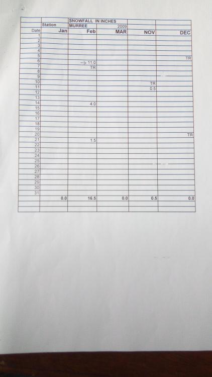
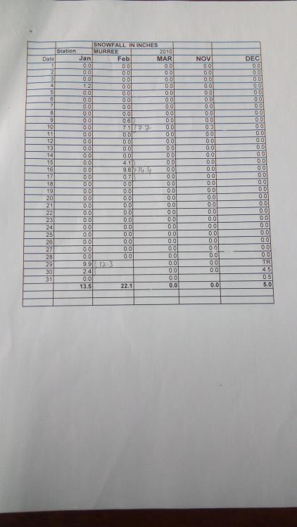
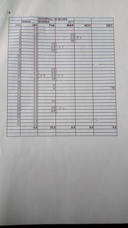
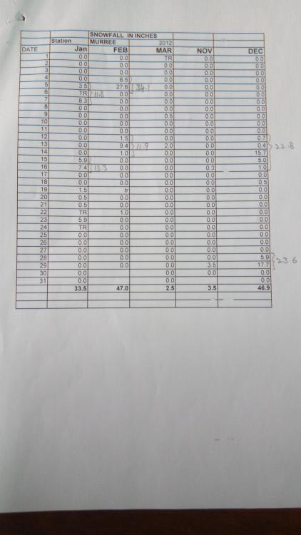
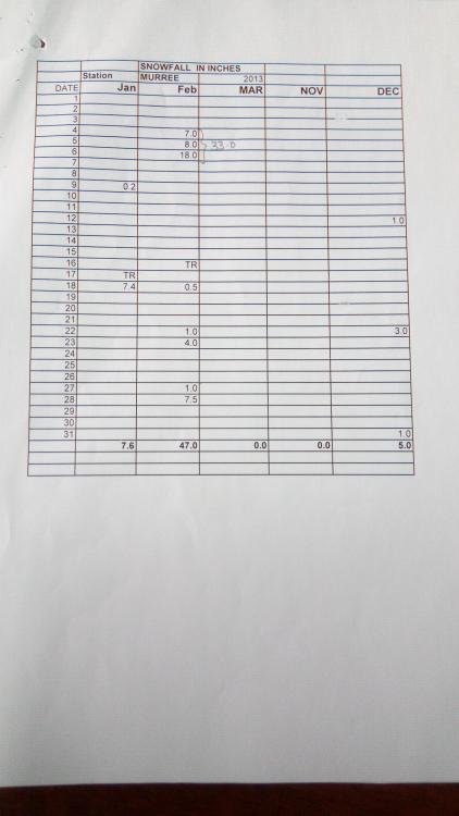
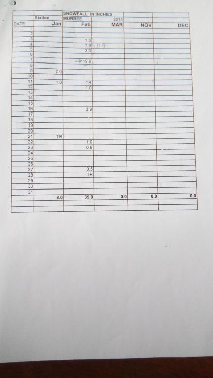
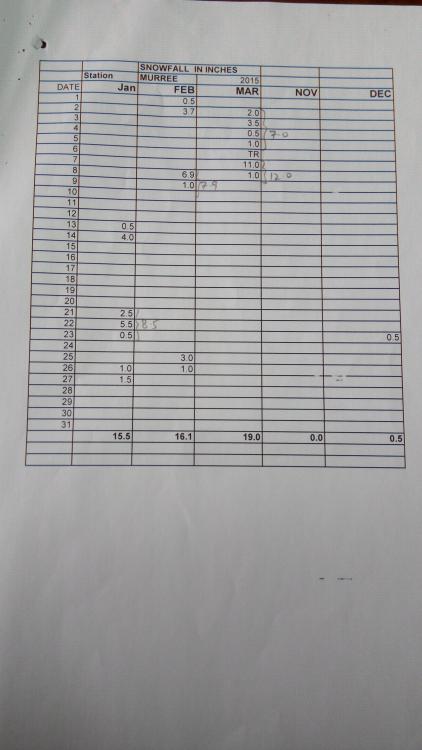
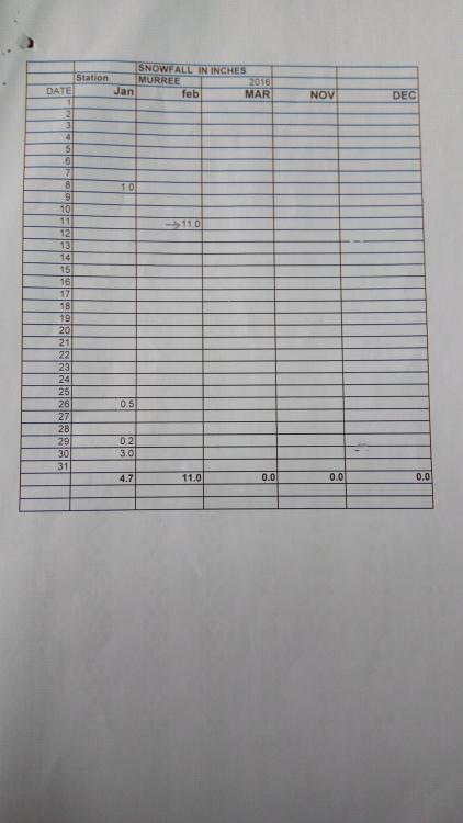
AA. Some progress has been made in this connection and snow fall data regarding Murree area has been collected from Met Department. According to the received information, only 'Number of Days of Snow Fall' data is available for the years from 1973-2004. However, daily recorded snow fall thickness in inches is available for the years from 2005-2016. According to this data, calculated maximum snow fall in one go of 4'-9" was observed in Murree during Feb 2005, whereas 2nd highest snow fall of 4'-1" was observed in Jan 2005. Images of year wise snow fall record from 2005 to 2016 are attached below, for the benefit of all. Regards.
-
AA. I am analysing a 2B+10 RC structure, located in seismic zone 2B on ETABS 9.7.4. The image showing the runtime error, displayed by the software is attached below this post. My questions are as under: a. Why might be the source or reason of this error? b. More importantly, how the affected element (indicated by the number 22836 in the attached image) can be located in the ETABS model? An urgent help is needed to sort out above problem. Regards.
-
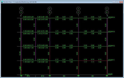
Picked up columns are different from normal RC columns in that at their lowest point, these are located on (picked up from) top of a beam at some upper story of the building & transfer the load to the supporting beam, instead of trasferring it to a lower column directly. In the following image (showing elevation view of an ETABS model, where vertical purple lines represent columns, and horizontal lines represent beams), second column from left, is a picked up column. It is starting from top of a beam at first floor level, unlike all other columns stsrting from the 'base' i.e., ground level.
-
Yes.
-
See the following links for clarification: 1. Load pattern 2. Load case 3. Load combination Regards.
- 1 reply
-
- 2
-

-

-
- load cases
- loadcombinations
- (and 1 more)
-
In general, compressive strength of concrete cubes increases with the decrease in size of the cube. The same is also true for the cyliderical specimens having same height-to-diameter ratios. In this connection, results of an interesting research study are available at the following link: http://scialert.net/fulltext/?doi=jas.2011.584.588 Moreover, the size & shape of the concrete samples (cube or cylinder) to be used for determining the compressive strength of concrete is specified in the relevant Concrete Design code. Although, generally 150x150x150 mm cubes are specified by the more common design codes, cube shaped or cylinderical specimens of other sizes may also be used for determining the design compressive strength of concrete, IF ACCEPTABLE BY THE APPLICABLE CONCRETE DESIGN CODE. Regards.