EngrUzair
-
Posts
476 -
Joined
-
Last visited
-
Days Won
242
Content Type
Profiles
Forums
Events
Everything posted by EngrUzair
-

Relation of static linear analysis and p-delta analysis
EngrUzair replied to Dauntless's topic in Seismic Design
Please refer to Sections 1629, 1630 and 1631 of UB97 for your required information. Regards. -
In case you need it for your office work, more appropriately you should ask your employer to arrange it for you. The link for purchasing the document, is given below: https://www.concrete.org/store/productdetail.aspx?ItemID=35006
-
The information given above is a bit dated with reference to both the ETABS version and the ACI code versions, as the above referred document pertains to ETABS version 7 and ACI 318-99. Whereas the ETABS 2015 & ACI 318-14 are the latest ETABS & ACI code versions in use today. (ETABS 2016 has been released a few days ago, however, AFAIK no changes have been made in it regarding present topic). As such, a little update correlating the previous & present situation, would be beneficial for all those interested. Here are my 2 cents: 1. According to ETABS Concrete Frame Design Manual, beam design in ETABS is done, a. As a Rectangular or T-beam, for the Maximum Positive Moment b. As a Rectangular beam always for the Maximum Negative Moment. 2. For ACI 318-99 and ETABS version 7, this is mentioned in 3rd paragraph under the heading 'Determine Factored Moments' on Page-37 of the reference provided by Ayesha earlier. 3. The same beam design principle has been followed in later ETABS versions (including ETABS 2015), for the later ACI code versions (including ACI318-14). 4. For ACI 318-02 and ACI318-05, this is indicated in Section 3.4.1.1 of the relevant ETABS Concrete Frame Design Manual, whereas for the newer ACI codes (2008, 2011 & 2014 versions), it is given in Sections 3.5.1.1 of the following ETABS 2015 Manuals for the mentioned ACI codes: a. ETABS Concrete Frame Design Manual (ACI 318-08) b. ETABS Concrete Frame Design Manual (ACI 318-11) c. ETABS Concrete Frame Design Manual (ACI 318-14) 5. Concrete Frame Design Manuals for the ACI 318-08 and earlier ACI codes, are generally installed along with ETABS 9 software, and are available in 'Manuals' sub-folder. Regards.
-
The referred code clause is Section R10.10.4.1 in Commentary portions of both ACI 318-08 as well as ACI 318-11.
- 16 replies
-
- 1
-

-
- stiffness modifier
- cracked section
- (and 2 more)
-
Try the following link: https://www.google.com/?client=firefox-b#q=designing+and+analyse+of+pile+foundations HTH Regards.
-
No, in case the inclusion of live load in Mass Source is not required as per your applicable design code, and other parameters including 'Additional masses' have been correctly applied. Otherwise, yes. Replies to your other questions and doubts are available at the following link: http://docs.csiamerica.com/help-files/etabs/Menus/Define/Mass_Source.htm Regards.
-
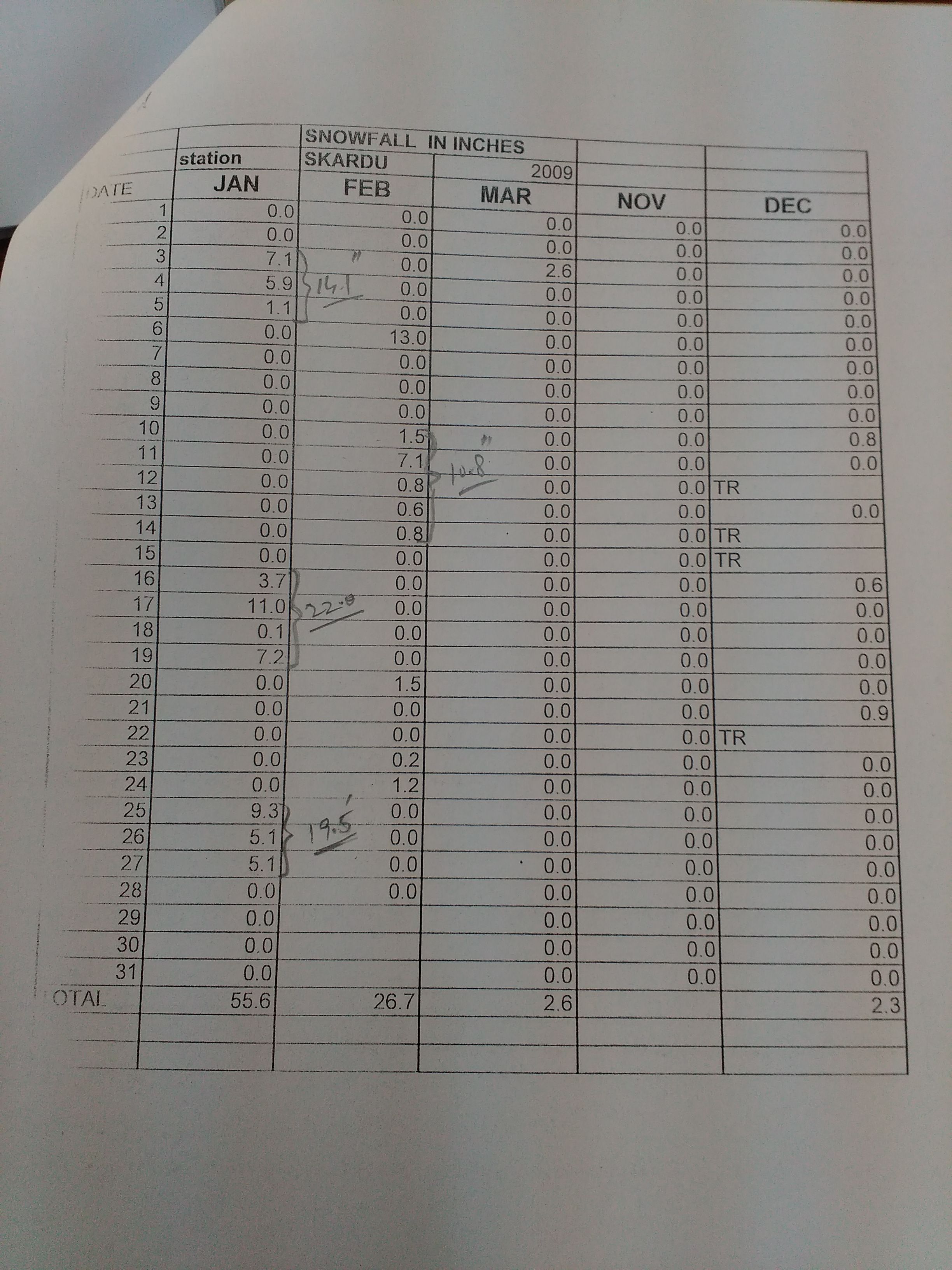
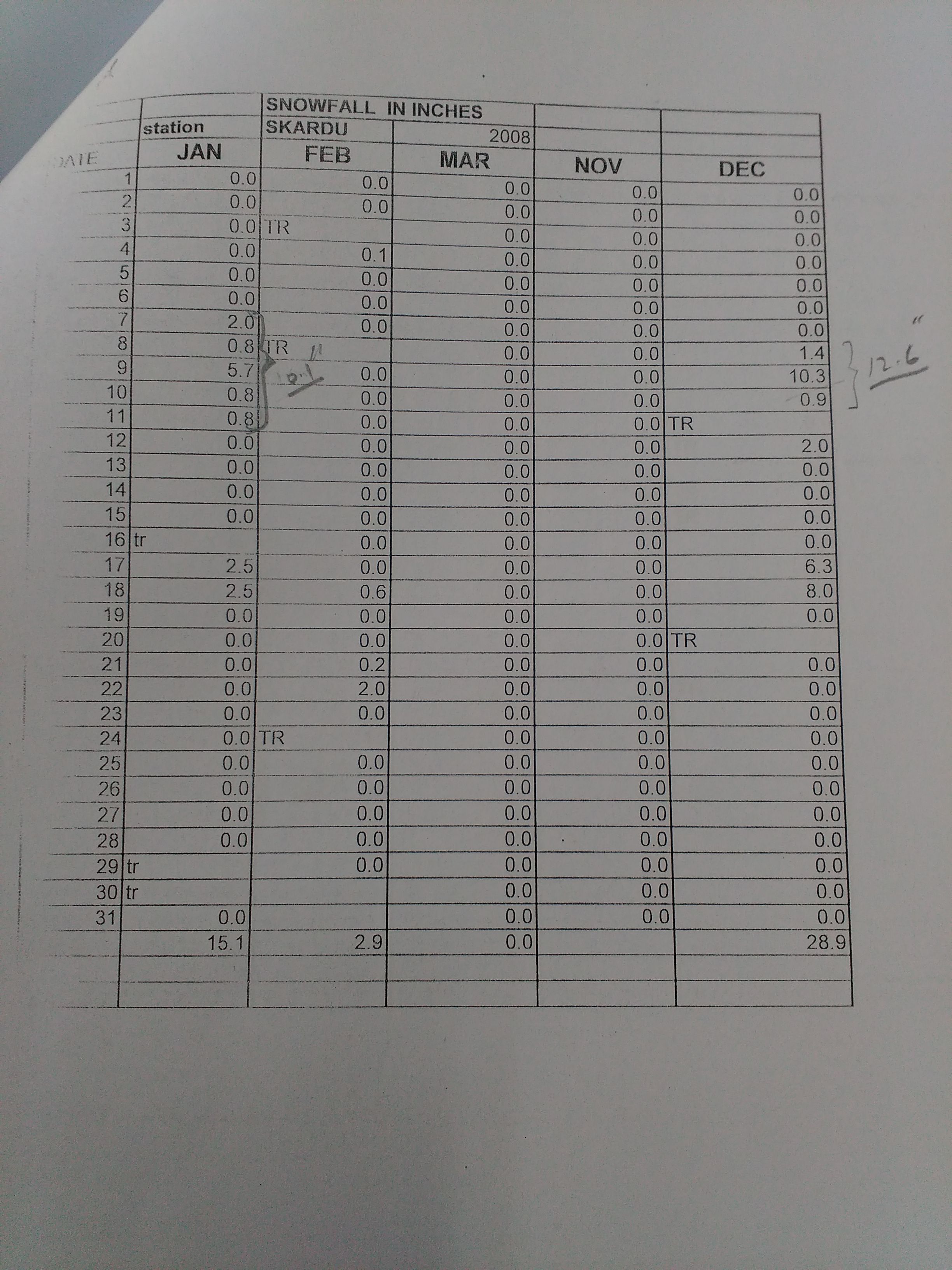
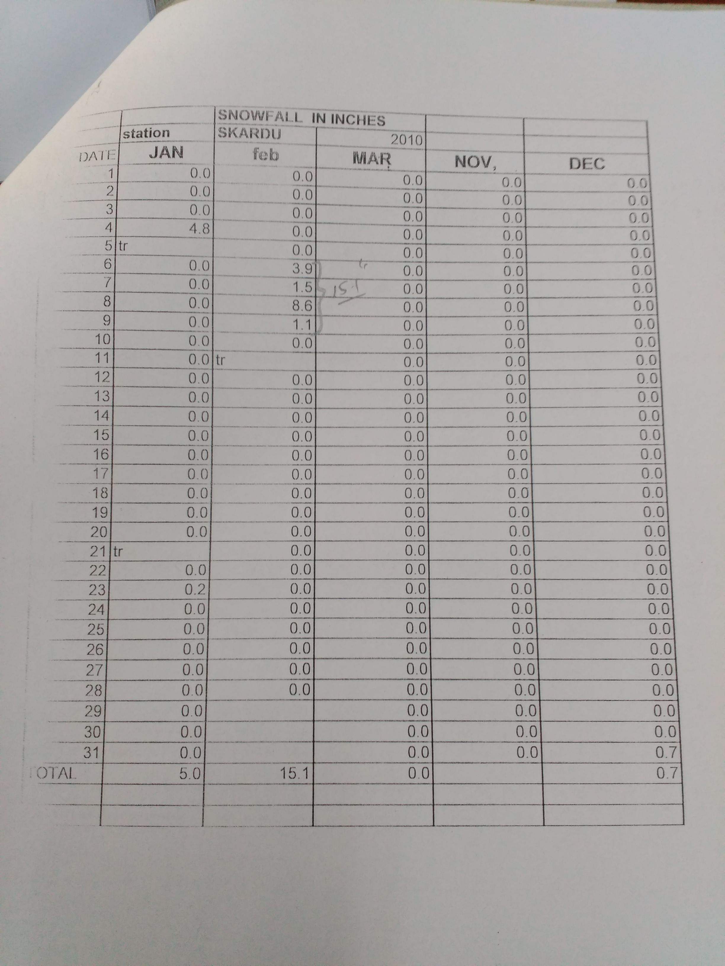
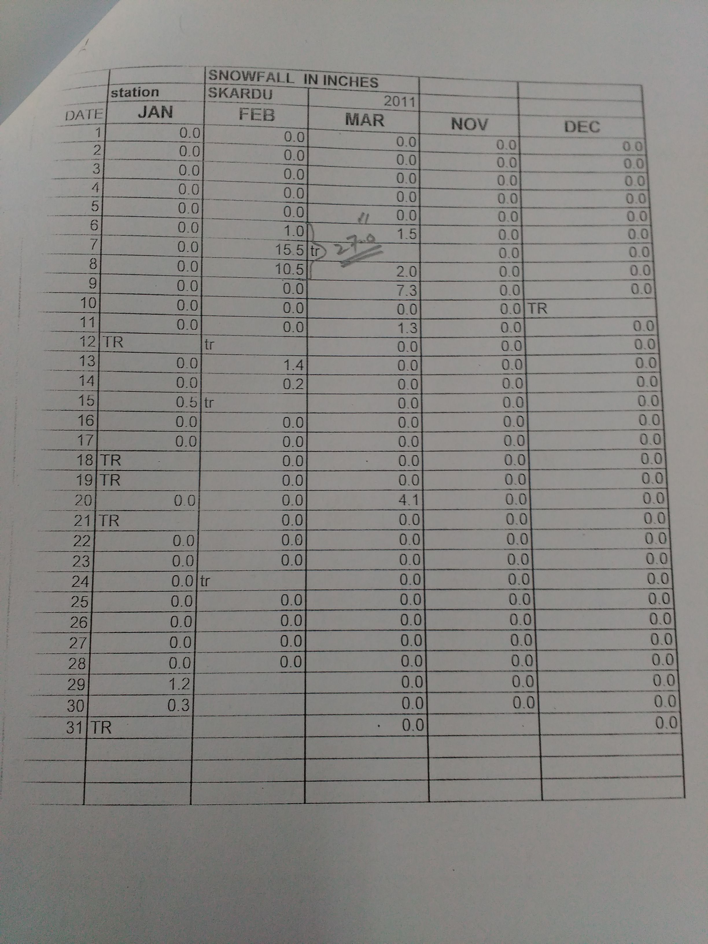
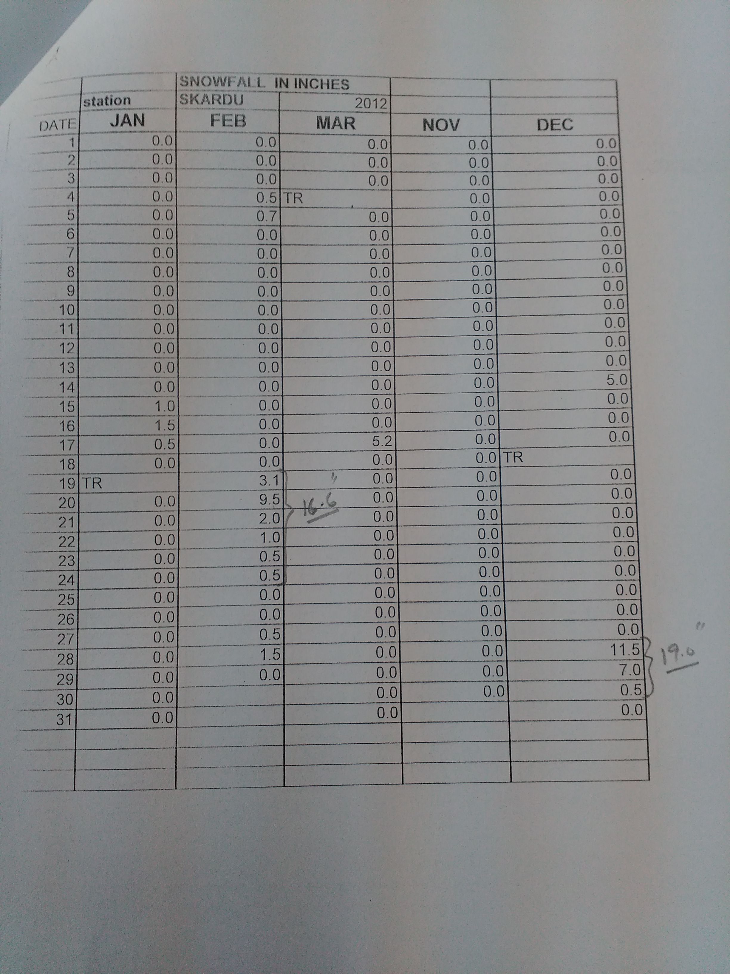
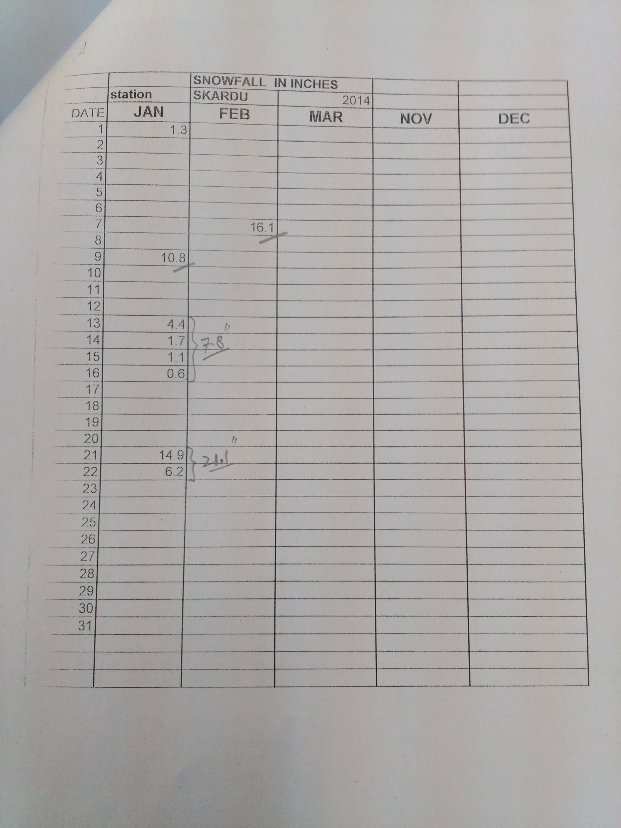
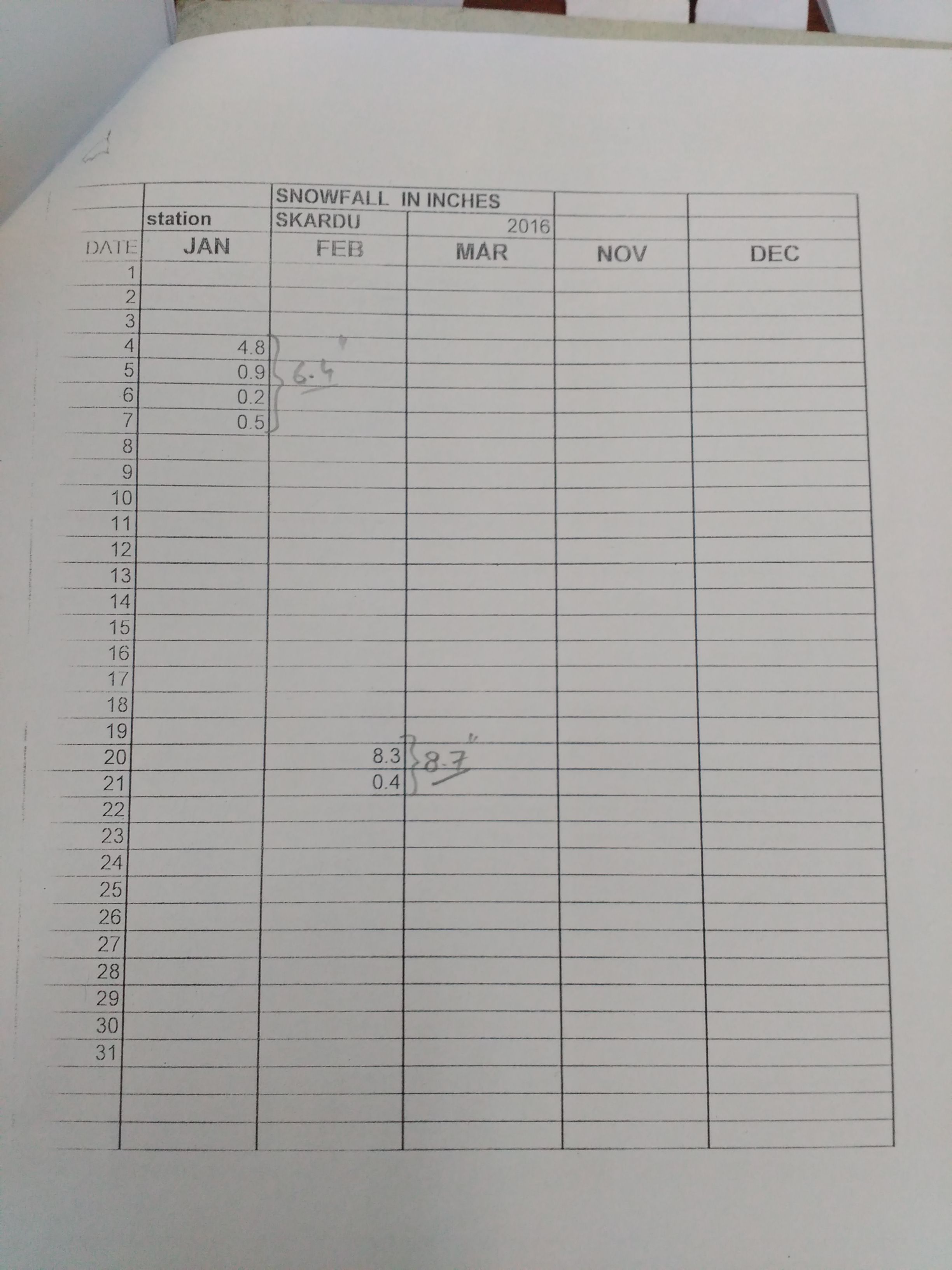
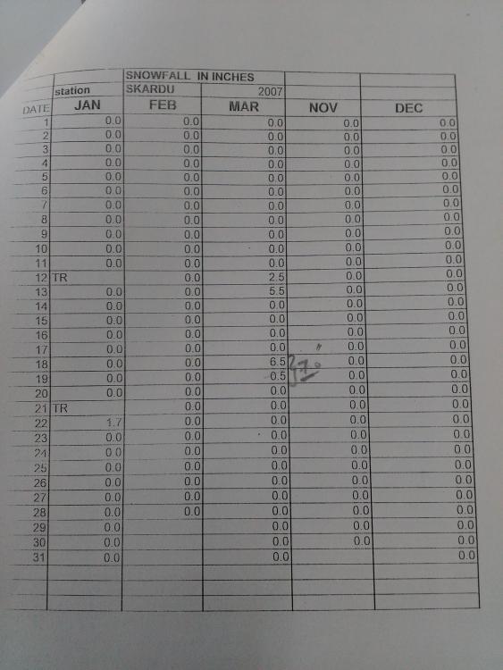
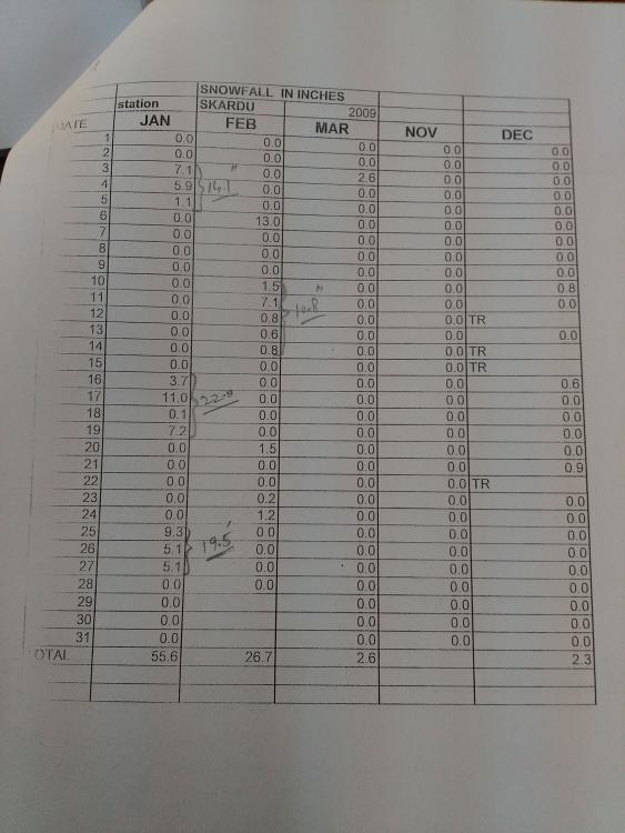
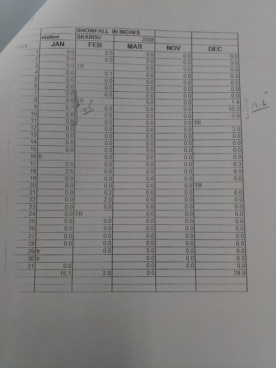
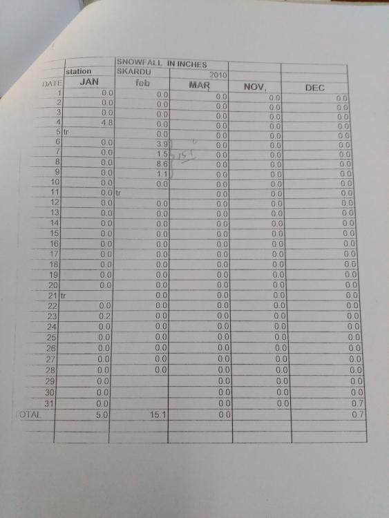
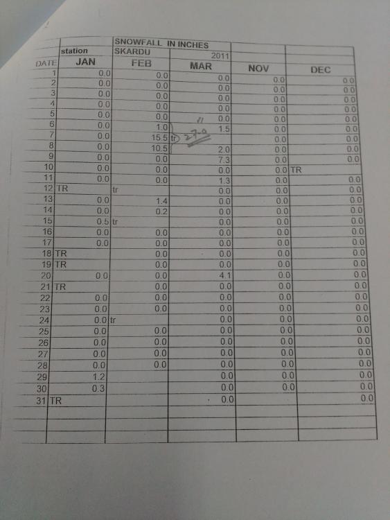
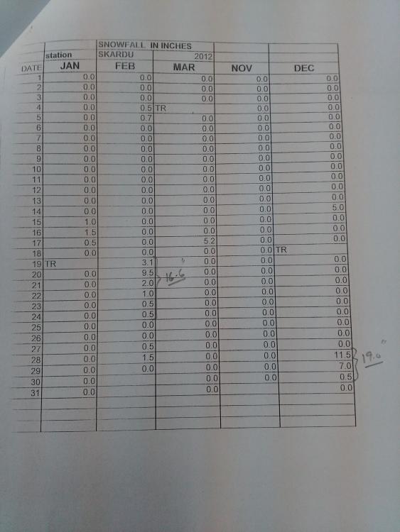
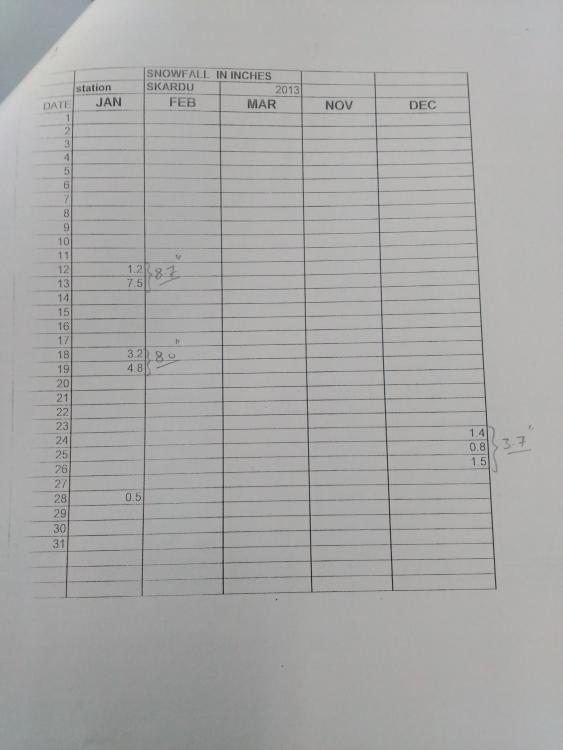
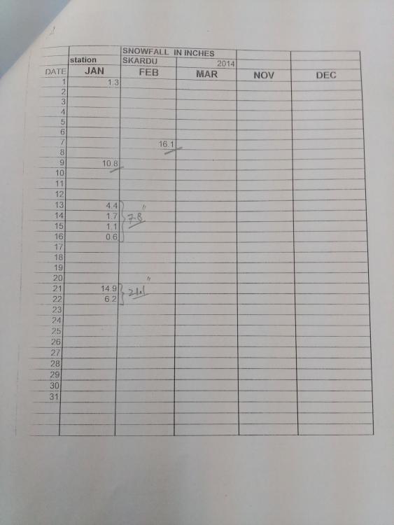
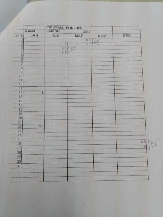
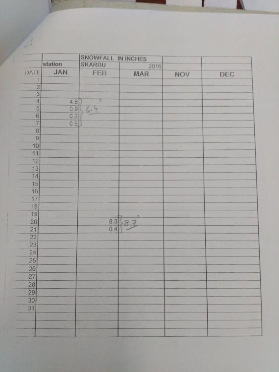
Aoa. I have received snow fall data of Skardu for the last ten years, in connection with a project. It is attached here for the benefit of all. Regards
-
Unable to apply line loads on concrete slabs in ETABS and SAFE
EngrUzair replied to spatio99's topic in Software Issues
You may provide dummy line members (beams) along the slab edge in your ETABS model and apply cladding load to these dummy beams. For a better distribution of loads, slab should be meshed suitably, and the the dummy beams should also be divided along the relevant joints of the meshed slab. After analyzing the ETABS model, the slabs may be exported to SAFE, if required. -
Yes, these numbers represent the beam width & total height. To understand this term correctly, you will need to attach longitudinal section details for the concerned beams RB1, RB2 etc (these are the sketches, similar to that you have attached for the beam 1B1 in your another post ), These should be available in your structural drawings. As per my understanding, the alphabets RB denote 'Roof Beam' here. The numbers accompanied by RB indicate the presence of beams, whereas others provide some other details (e.g., difference between levels of slab & beam etc). This might be clear from rest of the structural drawings. Regards.
-
Assalam-o-alaikum! Happy Independence day to you as well. Happy Independence day to all Pakistanis in general & SEFP members in special, whether they are in Pakistan or living abroad. May Allah bless our beloved country & help us in making it a better living place for all of us. Regards.
-
PEC recognized universities of pakistan
EngrUzair replied to Iqbal E Mohammad's topic in Students Zone
You may obtain your desired information from the following link: http://www.pec.org.pk/schedule_first.aspx# Regards.- 1 reply
-
- 1
-
-
WAA. From field point of view, it is better to keep the column reinforcement percentage to about 50% of maximum allowed by the code, as in the normal practice column main bar splicing is mostly done at one location, and at that location actual bar area would be doubled & it must not be more than the maximum permitted by the code. However, splicing may be staggered as well in compelling circumstances. I order to limit reinforcement percentage to desired level, you may need to increase the column sizes in the affected floors, or add shear walls at suitable places. You will need to model elevators to act as shear walls. Some people model stairs as well. I don't model stairs normally. Regards.
-
See the following link: https://www.google.com/search?q=waffle+slab+design+calculation&ie=utf-8&oe=utf-8&client=firefox-b Regards.
-
Dear Abid Qasmi, Refer to following links, for clarification regarding your queries: 1. https://wiki.csiamerica.com/display/etabs/P-Delta+analysis+parameters 2. Regards.
-
You may also specify to provide a suitable amount of camber in slab during construction, in order to balance the anticipated deflection.
-
In Pakistan, grade 36 steel is commonly available. Grade 50 steel might also be available. This can be decided properly after designing the structure, and making a comparison of material and fabrication costs. However, designing a beam or girder is a lot easier & less time-consuming than that of a truss. Moreover, fabrication costs are generally higher for a truss. In addition, you will need a higher roof, in order to accommodate greater required depth of a truss, all other parameters being the same. A truss may be preferable in some cases e.g., when a beam section of required size is not readily available in the market. However, this situation might not be governing factor in your case. Regards.
-
Selection of the size of a steel beam depends upon the design moment to be resisted and the structural steel grade of the beam material. Knowing these two parameters & design requirements of the steel design code, you can calculate section modulus of the beam required to resist the applied moment safely. Any steel section (e.g., 8"x4", 10"x5", etc.) having a section modulus equal or more than the required section modulus should be Ok to use, provided it satisfies all other relevant design & serviceability requirements of the applicable design code as well. Regards.
- 3 replies
-
- 1
-
-
- sandwich panel
- steel structure
- (and 1 more)
-
WA. Minimum reinforcement in raft or mat foundations is governed by ACI 318-08 section 15.10.4 & commentary R10.5.4 to ACI section 10.5.4. Requirements for maximum reinforcement are given in ACI section 10.3. Regards.
- 1 reply
-
- 1
-
-
- raft
- reinforcement
- (and 3 more)
-
Assalam-o-alaikum, Dear Colleagues! The Øresund bridge is an engineering marvel that connects the Danish capital of Copenhagen to the Swedish city of Malmö. A cable-stayed bridge runs nearly 8 km (5 miles) to an artificial island where it transitions into a tunnel that runs another 4 km (2.5 miles). The award-winning double-track railway and motorway opened on July 1, 2000. For more details refer to the following link: http://twistedsifter.com/2015/09/oresund-bridge-turns-into-tunnel-and-connects-denmark-and-sweden/


-
Wa alaikum assalam, Please refer to ACI 224.3R-95 Joints in Concrete Construction (http://www.dphu.org/uploads/attachements/books/books_2694_0.pdf) Moreover, following link also contains a very useful discussion on this topic: Regards.
-
This is related to Direct Analysis Method of AISC 360-05, given in Appendix 7 of Part 16.1 of AISC Steel Construction Manual 13th edition 2005. Application of this method, using ETABS, SAP2000 etc, has been explained in the following link: https://wiki.csiamerica.com/download/attachments/9538116/AISC360-05+Direct+Analysis+Method.pdf One-way of of checking practical implication of this message is to run the analysis & design twice. Once 'WITHOUT reiteration' and second time 'With reiteration' of analysis and design. Comparing the results of the two runs for the frame members affected by this error, you may very well be clear about how much crucial this error is. Please share the conclusions here too, for updating the knowledge of other forum members.
-
EI is the Flexural Rigidity of a structural member (https://en.wikipedia.org/wiki/Flexural_rigidity), whereas EA may be termed as the axial rigidity (https://en.wikipedia.org/wiki/Stiffness). Both the terms are related to the stiffness of a structure, as explained in above referred links.
-
See the following link: https://www.google.com/search?q=analysis+of+barrel+vault&ie=utf-8&oe=utf-8&client=firefox-b#q=analysis+and+design+of+barrel+vault Regards.
-
Relation of static linear analysis and p-delta analysis
EngrUzair replied to Dauntless's topic in Seismic Design
ASCE 7-10 Table 12.6-1 provides criteria for selection of Permitted Analytical Procedures for various Structural Design Categories, building heights and conditions. See Section 12.8 of ASCE 7-10 in general, and Section 12.8.7 in particular. Regards. -
designing foundations for the critical load combination
EngrUzair replied to mhdhamood's topic in Concrete Design
You may use your own custom made Microsoft Excel worksheet too, for this purpose. Regards.