

Simple Structures
-
Posts
103 -
Joined
-
Last visited
-
Days Won
41
Content Type
Profiles
Forums
Events
Everything posted by Simple Structures
-
Same rules apply for Steel AND concrete when it comes to splicing members. Although in concrete its reinforcement laps. Splices are expensive and hence you find the location with minimum bending and shear to splice at. With concrete its not splices as such, but bar lap lengths. The Canadian codes will have their rules for lapping reinforcement - for both compression and tension locations. 40 times the diameter of rebar is a good rule of thumb, if there are no codes available.
-
Design Codes: I am interested in hearing if structural engineers in Pakistan are undertaking design to European Eurocodes? Or is it all to the American Codes? The Pakistan Building code is not much use. (If you or your company are a Eurocodes design expert, then refer to my profile for contact details). I work overseas and see (and have used) many Structural Engineers and Consulting Companies in India who are proficient in producing design deliverable (GA drawings, detail drawings, analysis, calculations etc) to Eurocodes. They undertake designs for all European countries from India. Great for the company and the country. You can download guides for these codes free online. I would suggest you study Eurocode 1, Eurocode 2 and Eurocode 3 as a minimum to begin with. This will help guide you to design buildings safely, and give you lots of good background information. Each European Country, including Turkey and other countries like Malaysia, Hong Kong use Eurocodes for design. Great for you professional development. Also, Each country have their own National Annexe (specific parameters to the country) to go with these codes. I suggest in Pakistan you use either refer to Turkish or Malaysian National Annexes. Below are the codes (Eurocodes) I am referring to: Hope the list below is useful reference. Eurocode 1: Actions on Structures BS EN 1991-1-1: Actions on structures. General actions. Densities, self-weight, imposed loads for building BS EN 1991-1-2: Actions on structures. General actions. Actions on structures exposed to fir BS EN 1991-1-3: Actions on structures. General actions. Snow load BS EN 1991-1-4: Actions on structures. General actions. Wind action BS EN 1991-1-5: Actions on structures. General actions. Thermal action BS EN 1991-1-6: Actions on structures. General actions. Actions during execution BS EN 1991-1-7: Actions on structures. General actions. Accidental action BS EN 1991-2: Actions on structures. Traffic loads on bridge BS EN 1991-3: Actions on structures. Actions induced by cranes and machine BS EN 1991-4: Actions on structures. Silos and tank Eurocode 2: Design of Concrete structures BS EN 1992-1-1: Design of concrete structures. General rules and rules for building BS EN 1992-1-2: Design of concrete structures. General rules. Structural fire design BS EN 1992-2: Design of concrete structures. Concrete bridges. Design and detailing rule BS EN 1992-3: Design of concrete structures. Liquid retaining and containing structure Eurocode 3: Design of Steel structures BS EN 1993-1-1: Design of steel structures. General rules and rules for building BS EN 1993-1-2: Design of steel structures. General rules. Structural fire design BS EN 1993-1-3: Design of steel structures. General rules. Supplementary rules for cold-formed members and sheeting BS EN 1993-1-4: Design of steel structures. General rules. Supplementary rules for stainless steel BS EN 1993-1-5: Design of steel structures. Plated structural element BS EN 1993-1-6: Design of steel structures. Strength and Stability of Shell Structure BS EN 1993-1-7: Design of steel structures. Plated structures subject to out of plane loading BS EN 1993-1-8: Design of steel structures. Design of joint BS EN 1993-1-9: Design of steel structures. Fatigue BS EN 1993-1-10: Design of steel structures. Material toughness and through-thickness properties BS EN 1993-1-11: Design of steel structures. Design of structures with tension component BS EN 1993-1-12: Design of steel structures. Additional rules for the extension of EN 1993 up to steel grades S 70 BS EN 1993-2: Design of steel structures. Steel bridge BS EN 1993-3-1: Design of steel structures. Towers, masts and chimneys. Towers and mast BS EN 1993-3-2: Design of steel structures. Towers, masts and chimneys. Chimney BS EN 1993-4-1: Design of steel structures. Silo BS EN 1993-4-2: Design of steel structures. Tank BS EN 1993-4-3: Design of steel structures. Pipeline BS EN 1993-5: Design of steel structures. Pilin BS EN 1993-6: Design of steel structures. Crane supporting structures Eurocode 4: Design of Composite Steel and Concrete structures BS EN 1994-1-1: Design of composite steel and concrete structures. General rules and rules for building BS EN 1994-1-2: Design of composite steel and concrete structures. General rules. Structural fire design BS EN 1994-2: Design of composite steel and concrete structures. General rules and rules for bridge Eurocode 5: Design of Timber structures BS EN 1995-1-1: Design of timber structures. General. Common rules and rules for building BS EN 1995-1-2: Design of timber structures. General. Structural fire design BS EN 1995-2: Design of timber structures. Bridges Eurocode 6: Design of Masonry structures BS EN 1996-1-1: Design of masonry structures. General rules for reinforced and unreinforced masonry structure BS EN 1996-1-2: Design of masonry structures. General rules. Structural fire design BS EN 1996-2: Design of masonry structures. Design considerations, selection of materials and execution of masonry BS EN 1996-3: Design of masonry structures. Simplified calculation methods for unreinforced masonry structure Eurocode 7: Geotechnical Design BS EN 1997-1: Geotechnical design. General rule BS EN 1997-2: Geotechnical design. Ground investigation and testing Eurocode 8: Design of structures for earthquake resistance BS EN 1998-1 Design of structures for earthquake resistance. General rules, seismic actions and rules for building BS EN 1998-2: Design of structures for earthquake resistance. Bridge BS EN 1998-3: Design of structures for earthquake resistance. Assessment and retrofitting of building BS EN 1998-4: Design of structures for earthquake resistance. Silos, tanks and pipeline BS EN 1998-5: Design of structures for earthquake resistance. Foundations, retaining structures and geotechnical aspect BS EN 1998-6: Design of structures for earthquake resistance. Towers, masts and chimney Eurocode 9: Design of aluminium structures BS EN 1999-1-1: Design of aluminium structures. General structural rule BS EN 1999-1-2: Design of aluminium structures. Structural fire design BS EN 1999-1-3: Design of aluminium structures. Structures susceptible to fatigue BS EN 1999-1-4: Design of aluminium structures. Cold-formed structural sheeting BS EN 1999-1-5: Design of aluminium structures. Shell structure
-
Apologies - I did not log on for a few years! Therefore too late for your query! n the UK now they exclusively use Eurocodes for timber design: Eurocode 5 (previously it was BS 5268, the old British Standard)
-
Hi, After a few years break I saw a notification from SEP whilst deleting emails - hence I logged in today. Nice to see structural engineering technical deliberations are still going on with the same fervour. Credit to the Team who support this platform! Partition Loadings: 1. Buildings are designed to CODES or STANDARDS. Therefore decide which code are you designing to, and then use their recommendations. 2. Establish what type of partitions you have or will have? Is it a lightweight partition or will the partition heavy be in concrete block or brick. Acoustic, fire, party walls etc dictate the wall construction.. If its a speculative building (future floor uses unknown) then take higher loading. 3. Partitions in non-structural walls taking no vertical loading except for their self weight and finished, or occasional item (non-heavy) hung from the wall. 4. Generally 1 kpa = 1kn/sqm = 100kg/sqm covers most loading situations. This loading should be included as Imposed or Live loading in your calculations. Heavier partitions 1.5kN/sqm (blockwork). 5. As the building is many storeys high, and partitions are included as live loading, there are reduction factor for number of storeys imposed loading given by the codes when calculation foundation loading. Refer to the code rules when calculating foundation loading (for economy). 6. As a check take one floor with lots of partitions, and calculate the loading per sqm and then use that loading. Hope this helps.
-
Load Of External Precast Panels On Structural Frame
Simple Structures replied to SMAQ's topic in Concrete Design
.. and don't forget eccentricities and torsions when you come to design and detail the slab/beam edge. -
Remember the advice given by Einstein, "In theory, theory and practice are the same. In Practice, they are NOT". Get exposure to practical courses whilst you are studying...check out the post below as a starter....

- 1 reply
-
- 2
-

-
Modelling staircases in softwares for structural analysis
Simple Structures replied to SAL9000's topic in Concrete Design
Interesting question: 1. Yes you can model them as inclined shell, and detail the stair and slab connection accordingly. Half landings make the modelling and force transfer a bit tricky. 2. In many high rise buildings, the staircase is enclosed in a vertical concrete shaft (walls)- for fire protection reasons. Here the concrete shaft (housing the stairs and lift cores) tends to performs building stability function also. 3. Nowadays the core walls are cast by "slip-forming" hence many stairs are precast, lowered down into the shaft by crane and fixed to the shaft walls. In the past as the core walls were 'jumped' level by level, the staircases were cast in-situ with slab/walls. Speed of construction and project programme become a consideration too. 4. Apart from a structural engineering role, stairs also perform a safe protected fire escape route function, a legal requirement in many countries' building regulations, hence concrete or block wall enclosures are provided around stairs. 5. Therefore, if the staircases are cast in-situ (not precast) then detail and model them accordingly. -
Preferable construction joint location raft
Simple Structures replied to Waqar Saleem's topic in Foundation Design
@Waqar, you know how to keep the ball rolling..... 1. Remember: Dowels are good for shear transfer cases, whereas top and bottom reinforcement caters for flexure. 2. Many joints nowadays don't have a key - vertical edge between pours, provided you have good quality control and clean join with all paste removed and aggregate exposed - good bond. There is no need for two joints! 3. Joints at point of contraflexure (lower moments, higher shears) -
How to model a swimming pool at top roof of a building
Simple Structures replied to fahmi's topic in General Discussion
I note you are from Egypt? Think earthquakes. Swimming pools full of water on on top of roofs and earthquakes are not an ideal combination. So lots of technical 'other' considerations needed too. -
Raft Edges and Corners Overstressed
Simple Structures replied to Waqar Saleem's topic in Foundation Design
Whilst waiting for Waqar's response, here are my thoughts: It is common for geotechnical engineers to allow 20% overstress on bearing pressure due to transient (non-permanent) loading, i.e wind. For allowing 20% overstress of bearing pressures due to dead and superimposed live loading, I would expect the concrete raft to be stiffened along the edges (edge thickening) to assist with the spread over a wider area, and thus averaged out in terms of allowable soil bearing pressure and settlement? With 20% overstress there will be rotation along the raft edges too - that needs to be a design consideration. Also edges of rafts may be subject to erosion or softening of soil from say someone laying a draining pipe along the edge of the raft, or digging an excavation adjacent to the edge of the raft. Think in terms of building foundation performance - over its 50+ years life! The figure below is quiet interesting on simple pad footing case, and how pressure distributes under s a pad (sort of a raft), depending on soil type. Always good to get a geotechnical engineer's opinion on soil bearing pressure matters.
-
Blast Design - The secret is in assessing the loading correctly and detailing the structural connections properly. I worked on a nuclear bomb shelter many years ago in the Middle East and we used American Military Codes TM....to undertake the design. Also more recently since 9/11 blast loading from terrorist attacks has become norm for important buildings in western countries. The attached two papers will help you - one American, one European. I would look at the European JRC (Joint Research Centre) paper first. With blast each component fixing needs to be checked for the loading. Provided the structural frame is detailed properly with loading sharing redundancies in design and detailing (for accidental damage such as gas explosion where a column may be removed and structure must still stay standing) and with sufficient connections design (steel structures) or reinforcement lap lengths (concrete structures). Also in a wall add a secondary smaller size reinforcement mesh to control concrete cover thickness splintering after a blast. Make sure the façade cladding components are designed for the element loading, especially their connection to the frame. EU_Calcualtions of Blast Loads for structrual buildings.pdf Concrete buildings under blast loading_SU02003FU.pdf
-
Raft Edges and Corners Overstressed
Simple Structures replied to Waqar Saleem's topic in Foundation Design
Don't know the finer details of the model - have you tried thickening the edges of the Raft? or local thickening? -
Codes are written by Committee of Engineers and Professors of Structural Engineering - I know, because I have been involved. Then codes are then updated every 3-5 years, based on feedback and Engineers' experiences in the filed. So make sure you have the "latest" current and not out-of-date code version that you are working. The codes are then interpreted by Engineers based on their practical knowledge and experience. For example the UK Reinforcement detailing Manual is to be revised / published in December 2020 to EC2 detailing rules. I am part of the committee for this publication and we have sat in Committee meetings arguing our own interpretation of the code to derive a consensus on detail. All our L-shaped starter bars bend out! Pakistan does not such a "Engineers' Committee Structure" to provide guidance to young Engineers as far as I know Sepakistan is only such platform - well done to those who set it up! 1. Codes are interpreted by Engineers. Codes provide guidance only. You need to understand the internal tension, compression and shear stresses of the node you are designing and detailing - and then interpret the code to suit these to ensure the assumptions are achieved practically in the field too! 2. To put your mind at rest, you could use U-bars for columns starters to meet your interpretations of bending inwards (provided anchorage rules are satisfied), and then add smaller additional L-bars pointing outwards on the outside to keep the column starters square and upright. (We started writing a detailing manual for Pakistan and this is delayed as too much work on at present) I like your keenness to learn. Knowledge and experience make a good engineer.
-
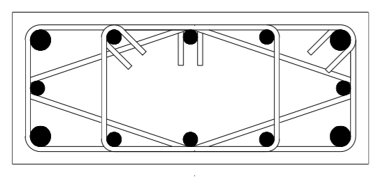
My few rupees worth of opinion on the matter below... Bending column starters inwards would lead to reinforcement congestion, very difficult to get concrete around the rebar - the best way is to get the draftsman to sketch the bars out to a large or full scale under the column - by sketching out the reinforcement under "small column cross section" one would realise that practically it cannot work! I always get joints (beam-column, column-base, corbels, etc) drawn out to a larger scale to ensure there is space to get concrete around the reinforcement / rebar. Also stability of column cage is also critical - hence bend outwards. Confinement of column concrete at base is achieved by stirrups / links - I opt for stirrups at 150mm (6') centres at lower end of columns (within base - cause no harm, and no worry either). Now, Lets look at 500mm (20") sq column - below - now imagine bending reinforcement inwards! .... practically impossible - always remember reinforcement only works if it only has concrete surrounding it! or 700 x 300 column

-
I am not a ETABS user but "base spring stiffness" follow the same rules for all structural analysis programmes, inc ETABS I would think. Base fixity is a determined by column stiffness : 4EI/L As column length (L) changes, the base stiffness changes. For a "nominally pinned base spring stiffness" take 10% of 4EI/L. For a "nominally fixed base spring stiffness" take 100% of 4EI/L. Nominal base stiffness explained.pdf

- 20 replies
-
- 1
-
-
- pin support
- fixed ends
- (and 1 more)
-
There is always dynamic loading. Use "lock-nuts" to stop bolt loosening.
-
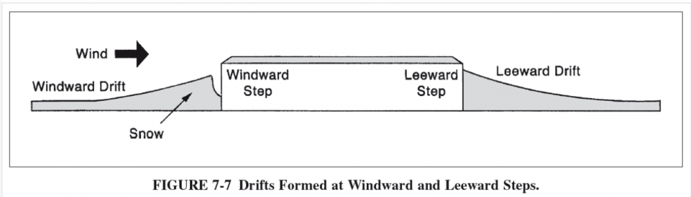
With snow loading design, always consider the "Drifting Snow" loading cases also - this often causes building failure.
-
Post Welded Base Resting on Levelling Nuts
Simple Structures replied to Syed Adnan Aqib's topic in Steel Design
1. Has overheating during welding (fabrication) bent the plate, before it arrived on site. Maybe the base plates was a little "thin" ?..or the weld too big...possibly the baseplate was bent at the outset? 2. Looking at the "close spacing of the HD bolts", tells me the designer is trying to get a "pin" base and forgetting that the bolts need to be spaced out.... this shows lack of HD bolt design experience to me? 3. The bolts are usually put in a "tube" for bit of bolt flexibility, with such close spacing of bolts (sleeve) would mean the concrete pull out cone would have low value? ... the designer does not realise sometimes higher temporary erection wind moments are generated and can be the critical base design case. 4. The plate is welded to column all around...then the bending under the spirit level means that one needs to look elsewhere for the plate bending phenomena? Normal Practice: a. Make the baseplate thicker than column flange at least - then increase thickness if needed for temporary erection wind load? b. The concrete is never at same level, so "shims" are placed on each column location by surveyor. c. Tight bolts and shims should be fine - if baseplate thickness and bolt design and spacing are correct. d. Complete WHOLE frame erection. Surveyor then checks "plumb (verticality) and align. If necessary adjust baseplate with steel wedges to get them plumbed and aligned. e. Once everything is in correct place, grout under the baseplate with "non-shrink high strength grout". Hope this helps. -
Most cold rolled purlin suppliers provide a design guide - one is attached. The purlins can be 'Z' or 'C' section, or hot rolled Angle section. They are always on a slope, hence the two-way bending etc. Purlins need to be designed for both "wind" uplift, and downward gravity loads.... and the case of net uplift! Make sure put in structs at mid span or sometime at 1/3 span, to increase load capacity etc. Also diagonal "anti-sag-rods" must be placed at bottom, and some at mid roof height to stop the Z-sections leaning down the slope. See attachment: steadmans_purlinsdesignguide.pdf
- 1 reply
-
- 1
-
-
The answer to your question is broadly YES. Normally the consulting engineer does frame analysis and provides joint / node forces to the steelwork fabricator (a specialist) who will have his own design office / connection specializing design engineer just designing connections. He will design the connection to suit (i) their workshop way of working, (ii) & how they will assemble (erect) the steel frame on site. In the western countries bolted connections are preferred on site, unless there is a special (architectural or other specific) reason for welding. Each country has its preference - where you are it may be different to the way its done where I am based. Here are few points to remember: 1.You assign the forces for the connection - shear, tension and moment as you get them from your frame analysis - and put them in a table on on the drawing for each frame (grid line) or each joint / node. On the drawing is best, give your +/ve -/ve notation. You state if the forces are factored (ultimate) or un-factored (working) loads. 2. Endplates to beams are always welded (most cases) in the workshop, and the beam and column connections are generally bolted on site location. 3. Welding on site in most countries is avoided as it requires good quality control system to be in place on site and also requires an experienced specially trained "coded welder" to undertake the work on site. 4. Avoid site welding at all cost - unless its the norm in your country. Bolted connections can also be designed as moment connection, and are used 95% of the time on site! 5. Give loads for each worst case, i.e Max& Min Dead, Live (Superimposed), Wind and Earthquake loading clearly stating whether loads are factored and un-factored and +ve -ve notation for avoidance of doubt. Connection designer will then combine them into the most onerous combination. 6. Lastly welded connection can be pinned also- diagonal wind brace welded connection has tension and shear forces - no moment. In a steel truss connections can be welded (or bolted) and there is pure tension or compression! Yes "connection design engineer" will know what to do .... you just give him the connection/node forces in tabulated form. Hope this helps.
-
I agree with BAZ. Also, apart from adding more shear walls, coinciding the shear centre of the building & shear walls may help. (Centre of lateral action vs centre of lateral reaction - minimise eccentricities where you can). As shear walls fail at the extremities, providing a reinforced column section at the two ends of the wall will also help. The additional concrete/reinforcement is beneficial. Shear walls are generally sized based on number and stiffness of columns. The more columns you have the more shear walls you need. Of the top of my head I cannot recall what that ratio should be.
-
Beam rebar development length requirement
Simple Structures replied to Rifat's topic in Seismic Design
Structural frame behaviour is dictated by joint performance - I often say structural design is joint performance design. The way you detail the joint (whether steel frame or concrete frame) will dictate performance of the structural frame. In a moment resisting frame the joints do all the work! Therefore, regardless of the code the beam reinforcement bar development length dictates the structural behaviour of the joint under lateral and gravity loading! As a minimum I would expect the beam tensile reinforcement embedment into the column to be approx. 40d - 40 times dia of bar. One of the best training is to read structural failure of buildings books and reports - lack of development length from beam to column cost of lot of lives in Pakistan 2005 earthquake I recall. -
After 30 years of designing buildings of many shapes and sizes, I still find interpretation of codes for specific detailed design issues require lot of engineering judgement and experience – and even from time to time clarification from those who have sat on committee that written codes on a regular basis! These findings are updated on subsequent revision of the code. Many 3-D software programmes have made performing structural analysis easier - provided you fully understand the fundamentals of structural engineering, member stiffness, joint releases, torsional restraints, buckling, shear interfaces etc. Believe you me they are both equally as important; you cannot design with one alone, without having a good knowledge of the other.
-
European Consultants working in Pakistan are using British and European Codes & Specifications for world bank funded projects. Indeed, there are projects usin both ACI & Eurocodes at the same time! India and Bangladesh and many other developing countries have their own structural codes - Pakistan does not sadly.... we like all things American it seems. Most Pakistan Engineers are using outdated American Codes int heir - as buying revised codes every few years is expensive - also working to imperial units (feets, kips, inches etc), rather than metric units (KN, mm, m). It is unlawful in the countries where the codes originate from to use "out-of-date" Codes! PEC - the authorising Engineering body - offers no advise, not does the Pakistan Housing Ministry! Check out this page of pase.pk website, where I have tried to offer some information on codes: pase.pk - codes Best to check and agree first with your Client on acceptable Codes and Specification documents to use on the project!
-
REVIT as structural analysis tool
Simple Structures replied to Tahmina Fahad's topic in Software Issues
Revit is ideally a DRAWING & BIM (Building Information Management) coordination tool. Most of the projects we work on use Revit Structure, Revit Architecture and Revit M&E - as the normal. Revit provides 3D drawing environment and whilst you input 2-D information, it automatically draws it as 3D. From Revit you can produce 2-D .pdf & .dwg files (same as AutoCAD). Revit is great for co-ordination all design disciplines (Arch,Eng, M&S, FFE etc) in one model so you can detect clashes and make sure the building is coordinated on plan - and therefore everything will fit on site without delay. It is also great for taking quantities and tonnage. It is the Drawing tool of the present and future (AutoCAD life is nearing end - although top universities in PK are still teaching AutoCAD and not REVIT. REVIT is basically a DRAWING TOOL. Its sister analysis programme is ROBOT. Although all analysis programmes are now compatible with REVIT for interchange of information. If you want to work overseas one day then learn REVIT. Start with the youtube link below, its easy to pick! https://www.youtube.com/channel/UCjaJieRt6okFy3wwXfuH9MA


