Simple Structures
-
Posts
103 -
Joined
-
Last visited
-
Days Won
41
Content Type
Profiles
Forums
Events
Everything posted by Simple Structures
-
Wise move to get the structural design and construction right. Many people are confused with the roles of the architect and the structural engineer. If you imagine the human body then the Architect decides on looks, colour of skin, how much fat, appearances generally etc. Whilst the structural engineer determines the bone structure (skeleton make-up), the joints cartilage, tendons etc.... and how the body stays stable under a heavy load, against strong wind loading, and even during earthquake ground motion. I am not sure if I can recommend someone on this platform - here to help. So... Hence, I have forwarded you an email details of someone who will able to help with Structural Design & Drawings complete. Visit: www.pase.pk Normally: This is what you need: 1. Architectural layout and elevations - By an Architect or prepared by yourself. 2. Structural design and detailing drawings and specification (inc foundations) - Structural Engineer can only do that - not an architect! 3. Drainage Design & Details - can also be drawn up by most structural engineer - normally public health engineer. 4. Electrical & Mechanical design (sockets, switches, lights AC etc locations are normally picked up on architects drawings) - by electrical/mechanical engineer, or yourself if you know what you want and where. Hope this helps,
- 1 reply
-
- 2
-

-
Max Percentage of steel in Columns
Simple Structures replied to Osama Anwar's topic in Concrete Design
@kHURRAM ALImakes a good point about staggered laps. Staggered laps are a good practice on columns, beams, walls and slab. 1. The reinforcement arrangement should be always be staggered to avoid, or reduce likelihood of large cracks or spalling. 2. The staggered laps should not be located in areas of high moment. This is what Eurocode EC2 guidance is for column - 4% max generally, to 8% max at laps (although this is always less in reality by staggered laps) . Columns have to be designed to be ductile and hence limits apply. The concrete takes compression load, whilst reinforcement takes tensile loads. In slender columns the failure is most case is due to bending. Therefore best to stagger laps for better performance. There is a technical reason behind these max limits so best to work within them, otherwise also difficult to prove otherwise to checking engineers and authorities.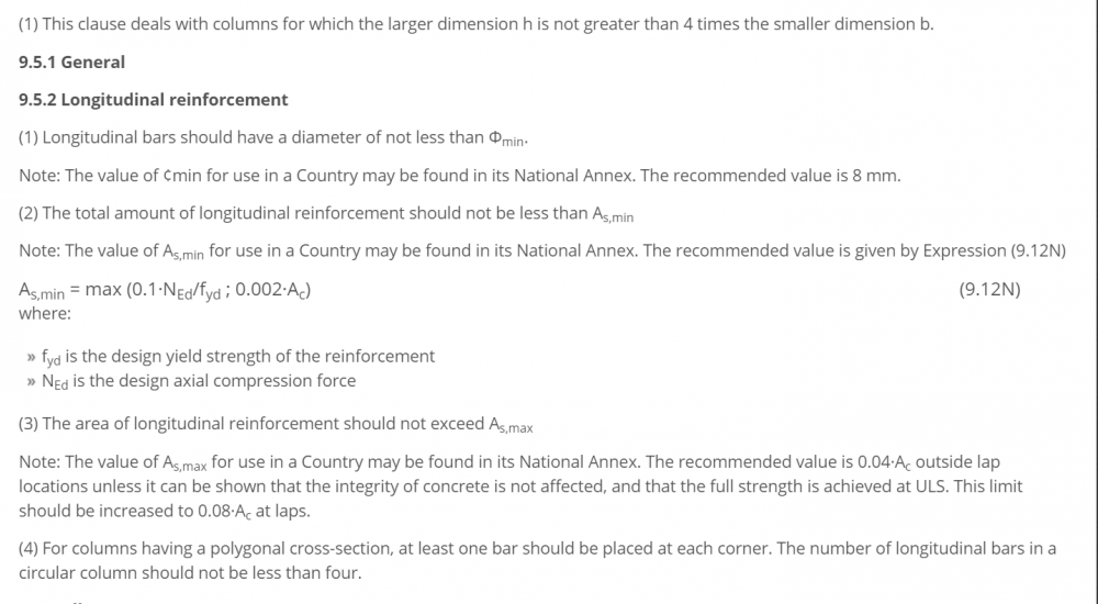
-
1. Material properties from Manufacturer/Supplier of steelwork section, i.e Steel Mill. This information is trusted in the West (however, in South Asia, just double check that the certificate is genuine) 2. Welding and connections verification /certification by Fabricator or the testing Company he has used, if independent checks are done.
-
Where I am working, all steelwork (structural steelwork sections & reinforcement for rc) come with manufacturer’s test certificates etc. This verifies the structural grades. You can trust the paperwork. For structural steelwork the design code BS EN 1993-1-1 (Eurocode EC3) uses 235 N/mm² and 460 N/mm² steel grades in accordance with the following standards: 1. BS EN 10025-2: 2019, Hot rolled products of structural steels. 2. BS EN 10210-1: 2006, Hot finished structural hollow sections of non-alloy and fine grain steels. 3. BS EN 10219-1: 2006, Cold formed welded structural hollow sections of non-alloy and fine grain steels.
-
It is normal practice to test 10% of welds by NDT (Non-Destructive Testing). This could be either by Magnet Particle Testing (MT) or Ultrasonic Testing (UT). MT is good for structural steel as the steel has magnetic properties to allow this. All welds for structural elements should to be undertaken by trained and competent welder. These welders are trained and tested (certainly in Europe & US, not so in South Asia i find), and their work is checked regularly by Non-Destructive Testing (NDT) - i.e. visual inspection by someone who understands all aspects of welding, and is probably an experienced Welder who has re-trained to become a Weld Inspector., and is familiar with possible weld defects. Destructive Testing (DT) which is undertaken on samples, and inspected microscopically, is done on sample pieces only, and verifies the welders compentencies etc. In most building projects non-destructive testing (NDT) is undertaken: 1. The welder cleans and visually inspect his own welding; 2. Welding Inspector (QA) inspects all critical welds by visual inspection - 10% of critical members - say connections with high moments and tensile forces. 3. Standards: British (BS), European (EN), International (ISO) Standards: a. BS EN ISO 17640:2017 - NDT testing of Welds: This is the international standard for manual ultrasonic testing of fusion-welded joints in metallic materials thicker than or equal to 8mm which exhibit low ultrasonic attenuation. The standard’s guidelines detail specific testing techniques for metals that show weakened ultrasonic levels at temperatures of up to 60⁰C. It’s primarily designed for full penetration weld joints where both the welded and parent material are ferritic. b. BS EN ISO 5817 Welding: BS EN ISO 5817 is an international welding standard that provides guidelines on quality levels of imperfections in fusion-welded joints (except for beam welding) in all types of steel, nickel, titanium and their alloys. The purpose of this standard is to define dimensions of typical imperfections which might be expected in normal fabrication of fusion welded joints. It provides three sets of dimensional values to apply to a wide range of welded fabrication. They are designated by symbols B, C and D. Quality level B corresponds to the highest requirement on the finished weld. Several types of loads are considered, e.g. static load, thermal load, corrosion load, pressure load. The quality levels refer to production and good workmanship. BS EN ISO 5817 applies to joints with a material thickness ≥ 0,5 mm. It covers fully penetrated butt welds and all fillet welds. Its principles can also be applied to partial-penetration butt welds.
-
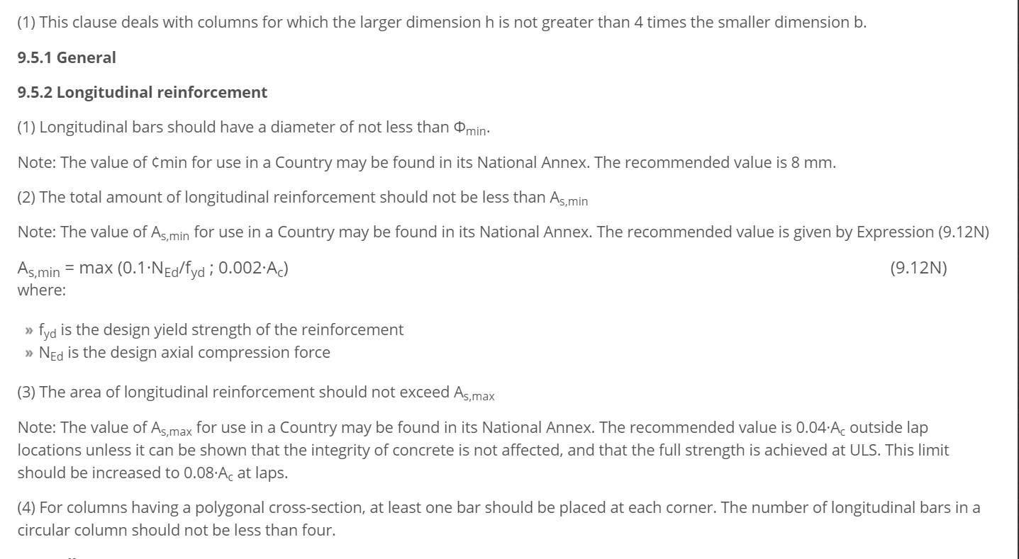
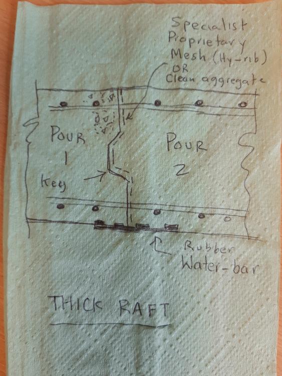
The joint will be same as any RAFT slab. Pour first section of slab, with key (1/3 depth) in the middle (I am assuming a thick slab) to interlock the two pours; Ensure a water-bar is placed below the joint. 1. excavate; 2. Pour 50mm (2") of blinding concrete to provide clean surface; 3. Install water proofing if needed; 4. Fix reinforcement; 5. Place a water bar at joint (to stop any water seeping through the joint); 6. Place end shutter at joint with a "key-way" to interlock the second pour; 7. There are proprietary mesh for such joints, but not essential provided all loose cement paste is removed, joint cleaned with pressure jet wash; 8. Pour other half of slab.
-
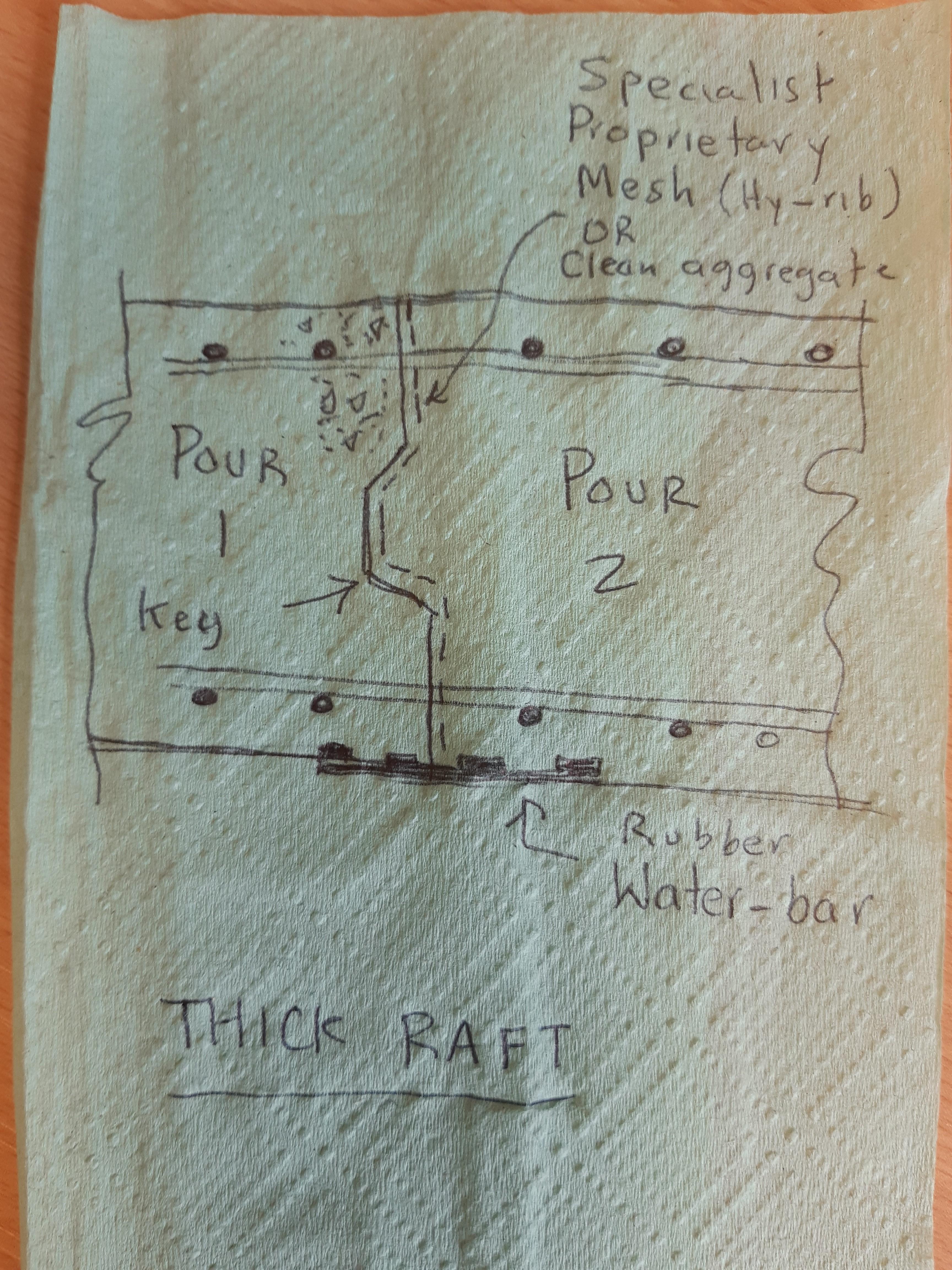
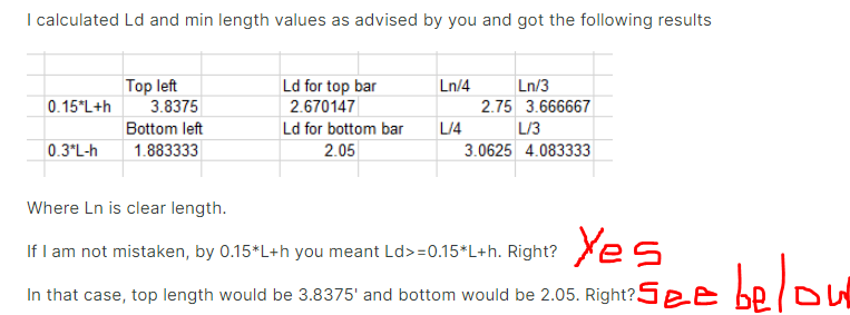
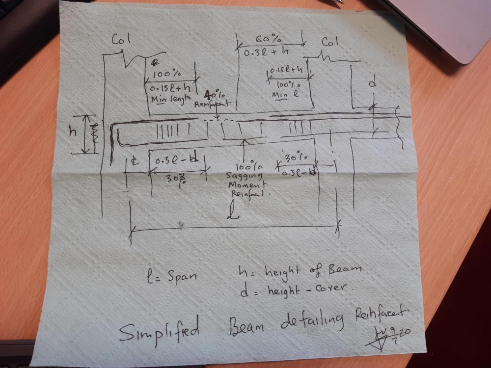
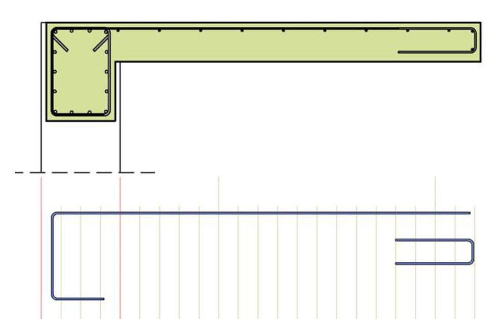
1. Apologies - I can only think in metric units - so ASSUMING all the above numbers to be metric units , for argument sake, Then, If L/4 = 2.75, then L = 11 m Therefore, 0.15L = 1.65m + depth of beam ..... which you say then totals 3.835m : This would mean your beam is 2.185m deep (L/5) which cannot be right! Get an Engineer in your office to check you numbers! With regards to rebar from fixed ends: Left or right , one would take 100% of the reinforcement for distance GREATER THAN 0.15L+h, then take 60% to distance 0.3L+4, and so on. You could decide to take 100% to 0.3L+h length. It depends how many bars you have in top. These are detailing rules are guidance and you as the engineer need to make safe choices based on that. For example, If you have 2 bars on top as 100% reinforcement, at say 0.15L+h you can splice them with smaller bars (60%), than after 0.3L+h, you can splice them again with small bars to take 40% etc. With so many splices, this is not practical, increases tonnage of rebar ... so based on ones engineering judgement, one would take the two bars to say 0.3L+ha and splice there with two small bars and just have two bars in top..... remember you have to do this from both ends, so it may be better and practical to take the 100% bars all the way across the top of the beam. If you had 5 bars on top, you can go continue with say 3 bars after the point beyond 0.15L+h (stop two there) and then you are continuing on with 60% etc. With seismic loading you will get M reversal at bottom (-ve M) so you may need to follow same rules for bottom bars. ------------------------------------------------------------------------- 2. Secondly, you must appreciate anchorage of top (& bottom) bars into the column needs to be sufficient to avoid joint failure. Calculate the anchorage length as shown "blue" on sketch below.... what the computer printout illustrates is inadequate! Your joint will fail under seismic loading .... or use long U-bars at ends in the beam. You must provide sufficient anchorage of beam bars into the column, both top and bottom bars.... Calculate anchorage length from centre-line of the column ! Master "reinforcement curtailment into the beam &, anchorage into the column or wall". 3. The BM envelope will come from gravity loads + seismic loads. Most computer programme give the BM diagrams envelopes for various load combinations. Like I say I am not a ETABs user, leave to that to others to advise. Below is an example - based on Eurocode EC2, the code i use - for beam pinned at LH side and continuous on the right... showing typical reinforcement curtailment based on BM. This is a general illustration only, and shows how BM Envelopes and Curtailment of reinforcement works. When I trained as a structural engineer I had to follow a training sequence and learn three things: 1. Work as reinforcement detailer/draughtsman for two years, then work out and draw bending moment diagrams by hand for another few years for beams and frames, and then design by computer!


-
Analyse on ETABS (and then detail drawing to L/4)- the extra bit helps during an earthquake dynamic loading - L/4 should be fine. I am not a ETABS user myself .... but am learning that its Pakistan's most favourite analysis programme....wow! As an engineer you should be able to calculate the MINIMUM anchorage (from previous information i sent you) and then always provide a bit more. My rule of thumb sketched below.
-
The attached may help Anchorage ACI 318 calc procedure.pdf
-
Opening in SMRF at Beam/Column Joint.
Simple Structures replied to Osama Anwar's topic in Seismic Design
Ok, I understand the educational side- so here is my thoughts on column spacing : Concrete frame columns are spaced normally between 6m(18ft) -8m (24ft), or even 9 m with deep or wide beams for normal rc floors. These can be lesser spacing than 6m too, if placed in wall between every room. Therefore place your columns at the locations shown.... away from openings in slab - Thus: Hotels often used "blade" or "rectangular" columns (600mm x 200mm - keep ration below 1:4, otherwise it becomes a wall and needs to be designed as such) so that they can be hidden within walls. So use rectangular columns rather than square ones, and they will fit inside walls, between rooms. (My tip: PK engineering community needs to get familiar with "metric units" , especially at your early career age - writing a dimension as "1 mm", is lot easier than writing it as "0.0393700787 inch"). Hope this helps.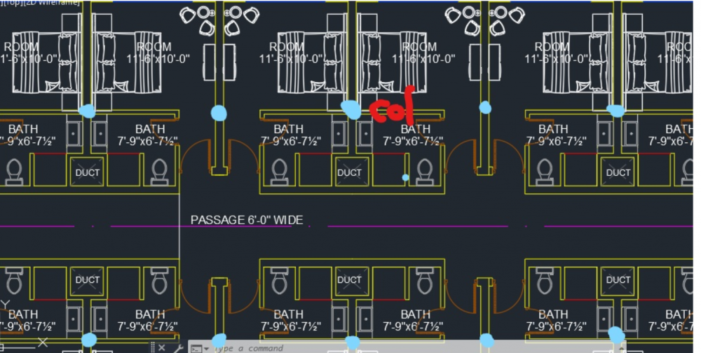
-
Opening in SMRF at Beam/Column Joint.
Simple Structures replied to Osama Anwar's topic in Seismic Design
Move the duct locations. An slab opening covering 50% of column perimeter is not a good idea. Provide a "dedicated services/duct riser" for all the ducts to run vertically, located near to lift or staircase walls, and run the ducts horizontally within ceiling void from there. -
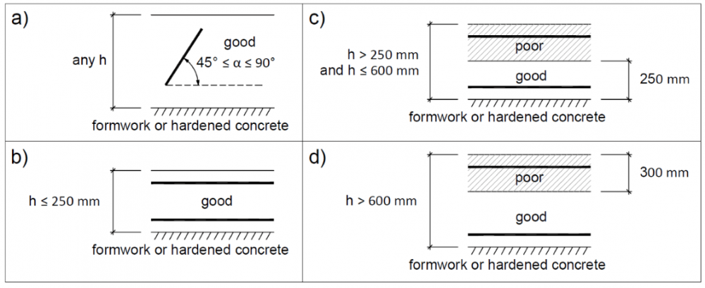
Designing buildings via such forums can lead to engineering failures - its a dangerous thing. This forum is for general advise, and then you as the engineer need to make the necessary engineering judgement based on your knowledge and experience. However, as rules of thumb: 1. Which code are you designing the concrete to? American or European? Follow the rules given in the code!! 2. Here is general advice, based on European Codes. For say 30N/mm2 concrete strength, and straight ribbed bars: ANCHORAGE: Good concrete/rebar bond conditions, good quality control: 40 x bar diameter; Poor concrete/rebar bond conditions, poor quality control: 60 x bar dai LAPS: 30 N/mm2 conc Bar laps, good bond, good conc quality control on site: 60 x bar dia Bar laps, poor bond, poor quality control on site: 90 x bar dia Below are defined "good" and "poor bond" conditions. If your slab is less than 250mm thick, then you have good bond condition, provided there is good concrete quality control regime on site. Quality is not something Pakistan construction sites are renowned for from my limited experience.
-
Engineering Body/society for CPD purpose.
Simple Structures replied to shazeb mirza's topic in General Discussion
Visit website : pase.pk , Pakistan Association of Structural Engineers - CPD sections. Plans are afoot by PASE to set up a formal CPD arrangement plan in place in due course. -
Rules of Thumb for Providing Reinforcement in Joints
Simple Structures replied to hali's topic in Concrete Design
@hali learn "anchorage" and "curtailment" rules for reinforcement of concrete structures. You will be there. -
Rules of Thumb for Providing Reinforcement in Joints
Simple Structures replied to hali's topic in Concrete Design
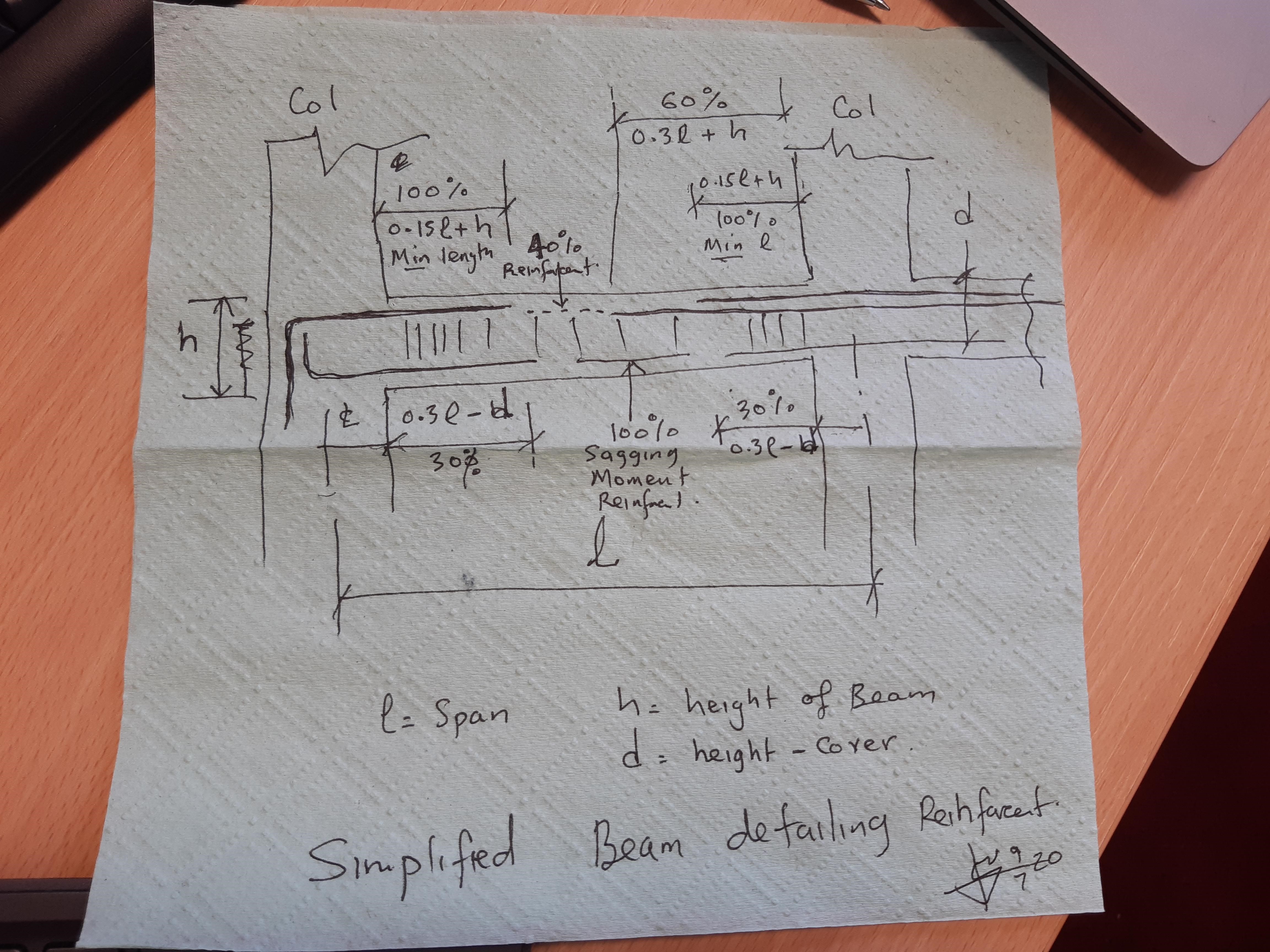
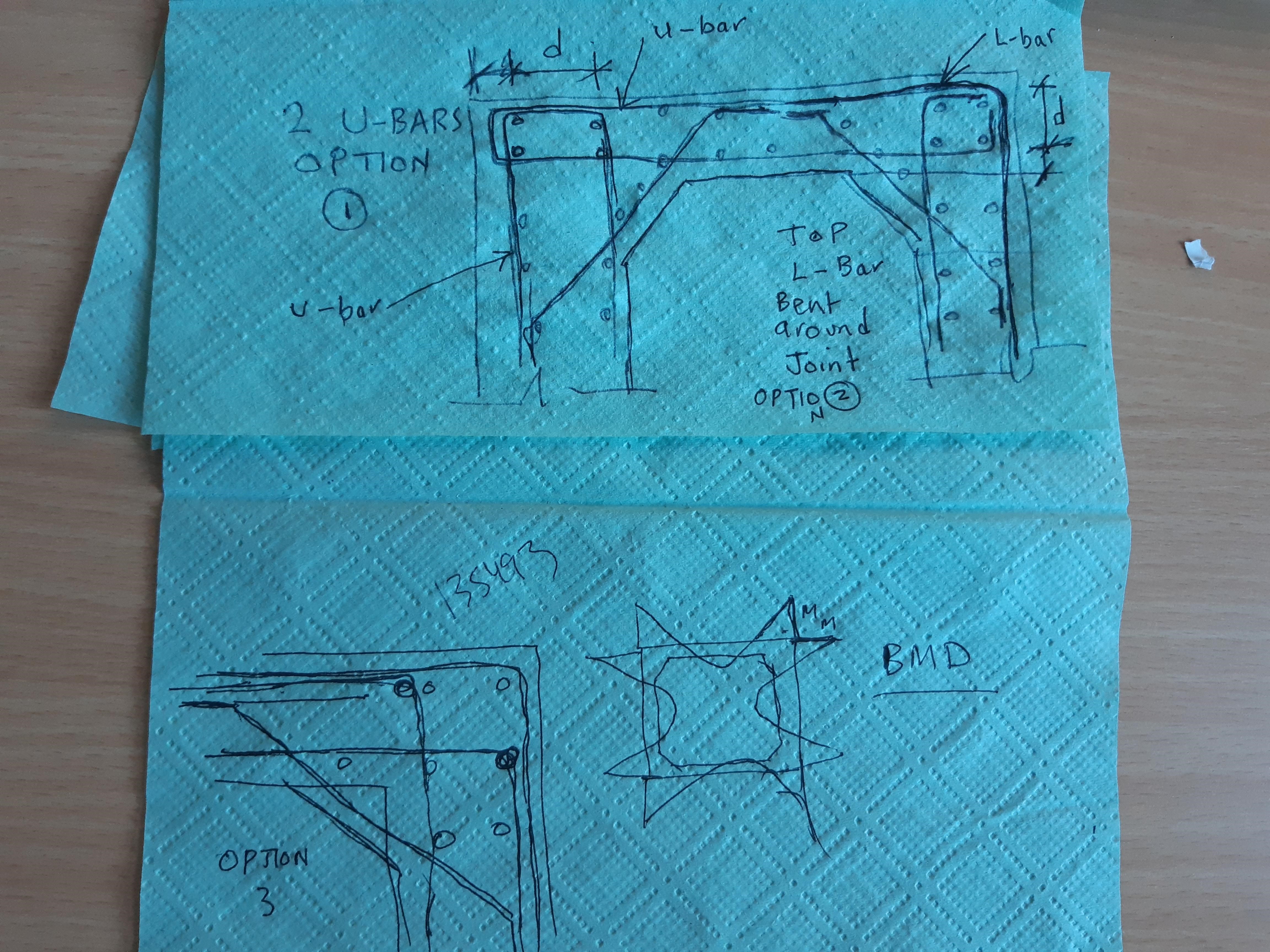
Culverts - first determine bending moment (tensile surfaces) and reinforce either one of two ways: See hand sketch below - once you know moment and effective depth of tension reinforcement you can design the joint. 1. U-bars coming in from slab and wall and connecting in corner. 2. or, Top/outer bar bent around the joint. 3. Option 3 is to use L-bars at joint, - see sketch below for all three ways you can detail a culvert corner - your engineering judgement is determine which detail best suits your design! Spacing of reinforcement tend to be closer to limit serviceability stress and hence crack width in concrete to <2mm - for reinforcement durability, and to stop water corroding the reinforcement, and to have a watertight structure; Movement joints are tricky in culverts. Make sure the concrete (or cement) selected is ok for, (i) against corrosive soils and (ii) chemicals in (waste) water.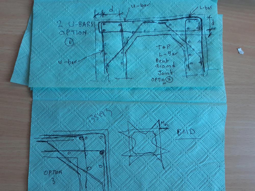
-
PS: I would model the connection same way you would a concrete column/slab connection and then "detail" the connection by hand to achieve the connection behaviour assumed in the analysis.
-
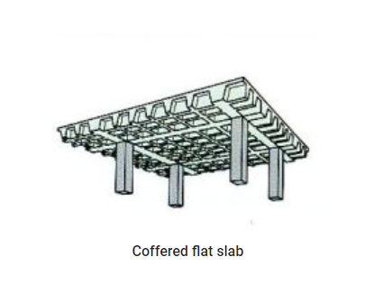
I think we are mixing a lot of things up here.... one must first feel comfortable designing a structure by hand, then rely on software. I will carry on with my previous numbering so you see the whole picture. 4. You must ask yourself, could I design a flat slab concrete structure by hand by determining moment and shear coefficients for continuous slab case for vertical gravity loading. This will give you both shear and moment value. Each CODE has rules for splitting the slab into "column strips" and slab strips" to determine width of slab for each hand calc. Decide which code you are going to use and follow its "design rules" for "flat slabs" / "flat plates". 5. With flat slab structure (no down stand beams) you will always require shear reinforcement in successive perimeters in the slab around the column. The exception would be if your column was say very large in plan size, or you thicken the slab around the column. Again, follow code approach, you should be able to do quick check by hand! 6. Next, how is the lateral stability of the structure achieved - shear walls or lift shaft? This is key as all lateral loads will go to these vertical elements via the floor slab diaphragm, limiting lateral load moments on the column at junction with slab. In earthquake regions i would plan lateral stability system first! 7. PT slabs require specialist PT tendons and grouts, quality control etc. They are often used to "thin" the slab section. They are expensive and require specialist installation. If you have all that (not sure if its economical for two storey building slab, unless it’s very heavily loaded, and has large plan area) then I would now even pursue this option. 8. Instead of PT slab, I would consider down stand beams to cut down slab span. There are various slab types which will span 9m (30'), or a coffered slab (designed same way as flat slab). 9. For your analysis, do not put in the 750mm long cantilevers, and design slab shear around the column. 10. Get the code, then the code handbook, then design. ETABS it seems to me have done a very good selling job in PK! Design is in three steps: Crawling (college and uni studies), then walking (understand all structural concepts and design concepts by hand) and then running (rely on software only when you can judge if the output is in the "correct ballpark", by looking at the results! a. Will span say 7-8m (24'), approx 300mm thick,no beams b. Will span 10m (30'), 600 o/all thick, beams within depth Or a (c) Traditional beam and slab system will suffice. Or (d) if you local expertise available, then use PT slabs (the tendons need to be protected during building life from any damage, say someone drilling a hole into the tendon during building life, and also special techniques are required to demolish PT buildings.

-
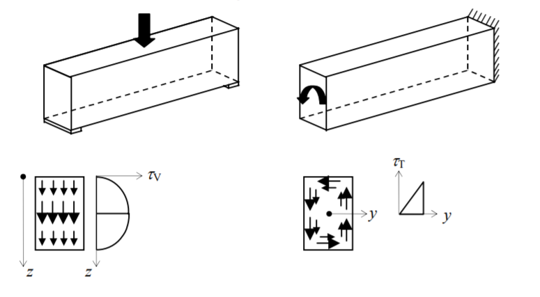
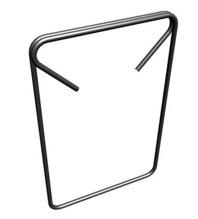
Good points made by BAZ & Umar. Just to add, there is more than one way to skin an animal, as they say – here is another approach to take. The third option would be not to put in "releases" and to "detail" the beam appropriately for torsion - this means the longitudinal bars in the beam may increase in size, and the links (stirrups) are detailed as torsion links. Transferring “releases” from computer software to the steel fixer on site can be tricky. Concrete behaves as you detail it! It is the combination of vertical shear and torsion that induce cracking and failure - unless the reinforcement (longitudinal & links/stirrups) are detailed to cater for it for it. In the beam there will be additional longitudinal reinforcement in the top, bottom AND SIDES to cater for any torsion. The figures below may help you understand the "practical" on site concept of catering for torsion with properly detailed reinforcement. 1. What is torsion: 2. Below is a torsion "link" or "stirrup" shape – what it looks like: Below is a torsional situation: In Pakistan always include a bar in bottom (shown red) of cantilever balcony ALSO, same shape as top bar, but bend up and around towards to top of beam/slab, to allow for load reversal during an earthquake! When I built my house in Pakistan, the steel fixer managed to bent one bar thus for the balcony - the workers in Pakistan (where material is expensive and labour is cheap) are very talented, but do not have the technical know-how sadly..... that's the challenge for the likes of you the structural engineer to disseminate down! Keep an eye on this forum. There is Pakistan RC Building Reinforcement Detailing Manual in preparation and will include this torsion detail now that it has come up here! This Manual be an advisory document but will assist both "young" structural engineers and reinforcement detailers (draftsmen) to understand reinforcement detailing and fixing! Passing down knowledge – think of it as “zakat”, then it gets easier then to give and share!


-
[HELP] ACI 318-14 to IS 456
Simple Structures replied to engroftheworld's topic in General Discussion
The attached will help you get started. Concrete Code India_is.456.2000.pdf Indian Seismic Codes_EQTip11.pdf -
Adopting Eurocodes in Pakistan
Simple Structures replied to Simple Structures's topic in General Discussion
@waqar saleemIf its any consolation, then PEC will not register me a a structural engineer in PK, due to some admin technicality. Having worked all over the world, and also in Pakistan for 2-years long time ago for a foreign company designing structural engineering works for Pakistan Govt ! etc - yet I don't tick some box so cannot be a structural engineer in PK ? I will get there eventually and am enjoying the experience of the little trivial mentality working against the betterment of the country, in the interest of their own ego & self importance. One of my problems is that I will not offer or take a penny in bribery, service charge or rishwat etc - so the path in PK will be much harder for me to travel, and I know that - am glad about my stance! Through PASE: - Pakistan Association of Structural Engineers - the change will come I hope for the profession in PK. I will pass on my 'practical structural engineering design and construction knowledge' to all Pakistani Structural Engineers, Insha'Allah. If I may say so I have had a lot of design and construction experience and now have guaged a good understanding of the 'Pakistan Structural Engineering' fraternity through this Sepakistan forum - which is the first green shoot for the profession in the country and needs watering more. Keep an eye on the website - pase.pk - The Pakistan Structural Engineer's Handbook of the future ? Believe you me, Structural Engineering Design is not rocket science. Its all about knowing where to find information - and pase.pk will help you find it. The issue for me is time, as I am also working full time! Simple Structures -
I have observed in the past 6-month that there is a real need to bring together and promote the profession of Structural Engineering in Pakistan. To start the process we are working on a platform PASE - Pakistan Association of Structural Engineers (www.pase.pk). This is a voluntary setup and the aim is to promote practical aspects of structural design and construction in Pakistan. We have started with a simple website, which s in early stages of development (baby steps). Interesting to note that the idea came about after a post in SEPAKISTAN. Whilst nothing is easy in Pakistan, (which makes the challenge more exciting), we aim to make inroads and bring the "Pakistan Structural Engineering Profession" to International Standards by knowledge sharing on real practical design and construction topics - so you can be equipped to compete with the right skills in both national and Internationally against other consulting engineers. For forum and discussions, the PASE website directs the visitor to this SEPAKISTAN forum....which i think works great, so congratulations to Sepakistan team - great set up guys. First challenge is to compile a "Pakistan Building Reinforcement Detailing Manual", and make it available on the website in the next few months(only started on it after a post in this forum a few days ago, will take a month or two to compile). The aim is to equip the Pakistani Structural Engineers with knowledge and information on "practical structural design" - that is at par with international standards. A 2-day programme of training courses and lectures was in the planning for October 2020 in Islamabad - but this has had to be postponed for the time being due to Covid-19 social distancing and travel restrictions. This may now probably move to later in the year or even early in 2021 - we shall see. The website: pase.pk (If you have issue connecting then google "Pakistan Association of Structural Engineers pase.pk") - we certainly are not IT professionals. Any feedback via the "contact" tab of the website from structural engineers would be welcome. Kind Regards Simple Structures
-
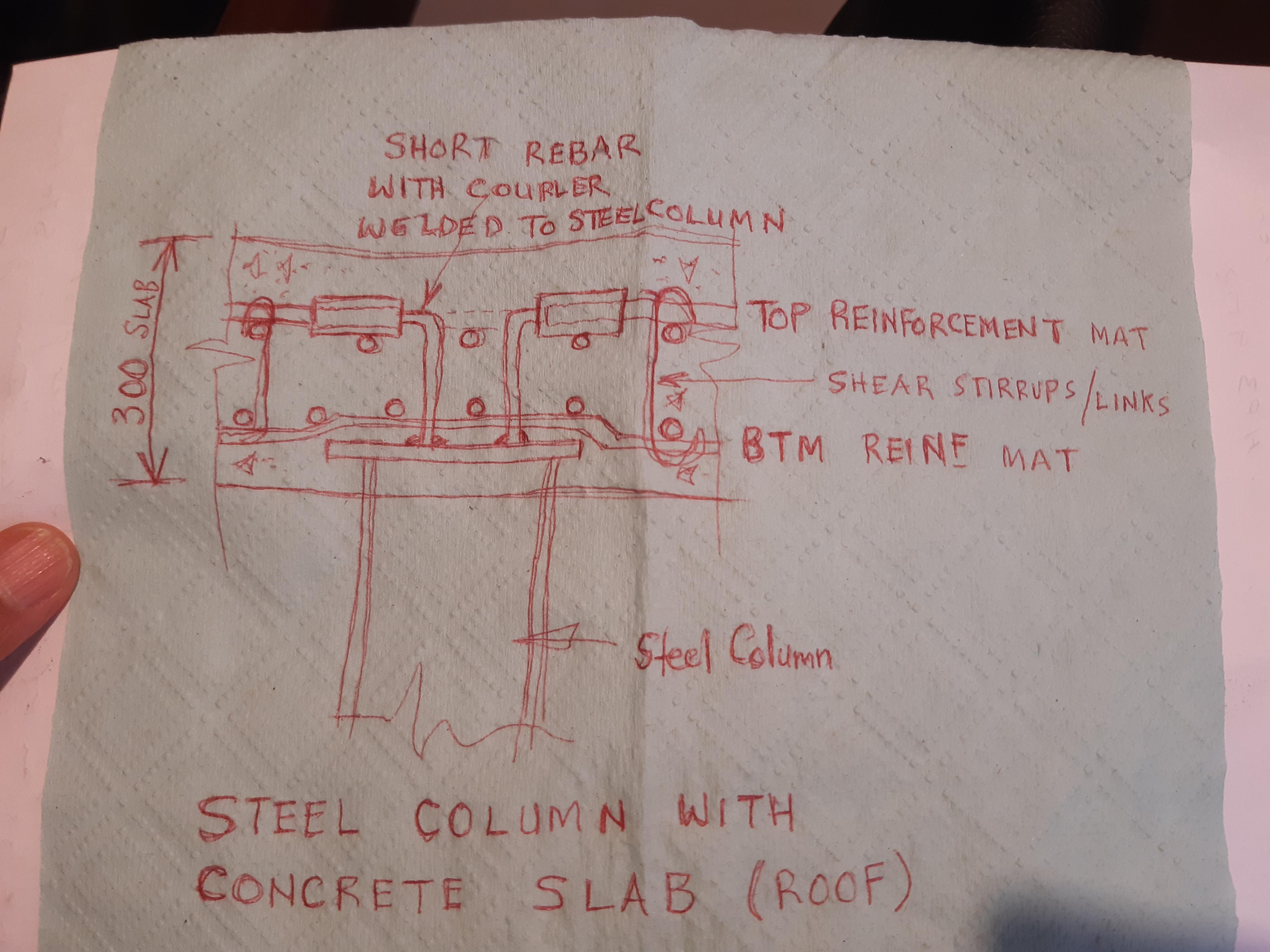
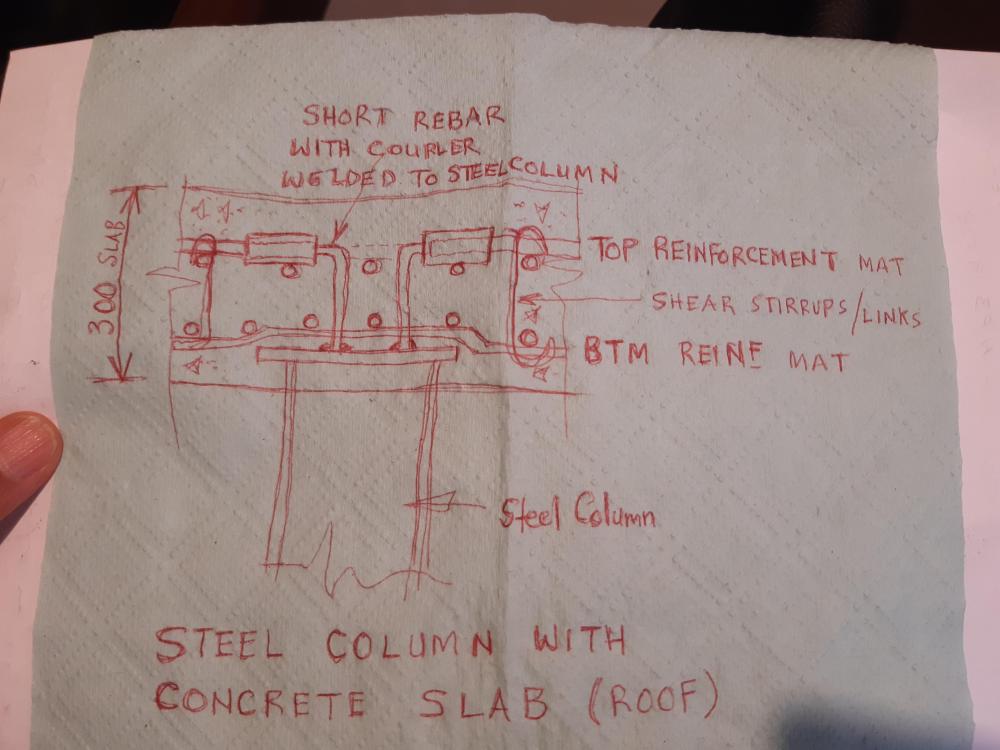
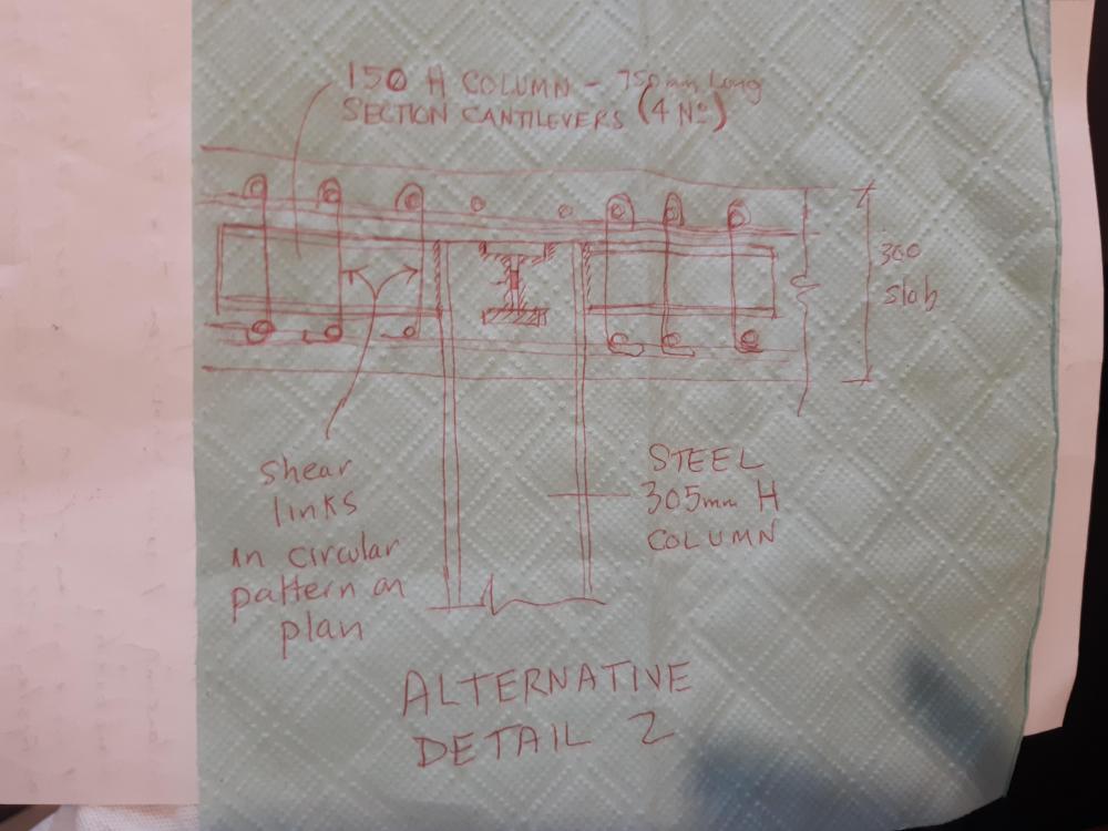
@M.Arslan Umar I attach two sketches which I did over my tea break: 1. Shows the steel column supporting a flat slab (flat plate) with no down stand beams. 2. Shows steel column with welded steel cantilever 750mm long beams cast within slab depth - no down stand beams. You can also carry the column above to the next slab level up. Structural Engineer - key design decisions 1. What design code am I designing to? ACI or Eurocode - follow their procedure for flat plate / flat slab design. 2. Make sue slab is deep enough to house steel sections. 3. The key thing with flat slab design to make sure there is shear links/stirrups in slab around the column - again follow code procedure! Sadly, Pakistan does not have code; Many practicing Engineers follow American codes - different versions ACI 318-19; ACI 318-11 etc. I prefer to use the Eurocodes - easier to follow for practical design! Sadly, in Pakistan we are obsessed with US stuff - status thing I think. Sorry about poor quality of sketches... done on the kitchen table on paper hand towels!
-
Working in Western Countries, one uses "splice couplers" or "headed bars" instead of laps to avoid congestion of reinforcement. The attachments are very useful read on such matters splice and development lengths for reinforcement - have a read. One attachment is manufacturers date, whilst the other attachment is on theoretical basis - in case you really want to get to the 'nitty-gritty' of the subject. In seismic design in most cases "tension laps" suffice. The Load Factor for seismic load is reduced to 1 (c.f 1.4 or 1.6 used in ultimate state normal design), the detailing is carried out to include load reversal scenarios, so the tension lap-work ok....some people multiply tension leaps by 1.4. Check yield stress of reinforcement, ductility properties, confining reinforcement (links or stirrups at closer spacing at laps, staggering laps, and so on. Pakistan Structural Engineers need a definitive "Concrete Buildings Reinforcement Detailing Manual for Pakistan" - following your post, I have asked someone to compile one ... one issue is lack of transparency from reinforcement manufacturers in Pakistan - We will get all data from 4 companies and compile one, will post "the manual" publicly on this Forum in due course - Insha'Allah within 3-months! (Note the data will be in metric units: mm, m, N/mm2 etc, so you need to get use to using metric units). If someone has "reinforcement data" or "tables" they currently use for concrete structures detailing in Pakistan, and are happy to share it, then please email them to me. Look forward to all contributions :-) - , sharing is caring about the profession in PK? SDH2_Chapter 10-Reinforced concrete structures.pdf US_Dayton-Concrete-Accessories-Rebar-Splicing-Handbook-1727463.pdf
-
If you are in Pakistan then i would be tempted to use "Precast Concrete Columns" rather than Steel Columns due to limited availability of heavy sections; Steel Sections are used for speed on construction. Nevertheless: I have designed a steel column / concrete flat slab (plate) configuration previously. This is your best course of action: 1. Decide which "design code" you will use for the design, and follow its procedure for slab shear check; This is key; 2. The steel columns will require short cantilever sections coming out into slab; 3. Make sure you can feed reinforcement through the steel section or above and below it and get adequate concrete cover; 4. Check slab shear - you will require lines of shear (vertical) reinforcement within slab, successive perimeters, around the column; Slab shear check around column is key!
-
Here are some general points for your information: 1. Weak Storey should be avoided in buildings where possible in earthquake zones, where large horizontal loads need to be catered for and transferred to the foundations. 2. Weak storey could occur where the walls at upper floors are omitted at a lower (first or ground) floor to create open plan space for retail or communal places. This is common in hotels, hospitals and Ground Floor shops in a plaza. 3. A weak storey occurs if the lateral stiffness of one floor is less than the 80% lateral stiffness of the floor above or below. UBC 1997 or IBC-2018? 4. The UBC 1997 is NOT a current code, obsolete (not used) in USA I understand, and this code has not been updated or technically supported since 1997 ( 23 years ago), and was replaced by the International Building Code - the current version being ICC IBC-2018. This code is updated every three years. Each update of a code brings above design rule changes, and therefore the latest code and version should be used. 5. In some Middle East, and other Third and other countries UBC is still around, and looks like being used, possibly because its the one they have in their library or office.