Simple Structures
-
Posts
103 -
Joined
-
Last visited
-
Days Won
41
Content Type
Profiles
Forums
Events
Everything posted by Simple Structures
-
Regarding Rebar Grade for Special moment frames
Simple Structures replied to kamruzzaman Shohug's topic in Seismic Design
The important consideration is ductility (elongation)of the reinforcement after yielding. Therefore provided the Grade 75 or even 80 can achieve the same elongation as a Grade 40 or 60 bar then that is fine. In Japan they use Grade 100 bars for seismic frames! In other countries reinforcement is classified as Grade 500A, 500B & 500C. The former (500A) being cold worked bar used for smaller diameters, Grade 500B for the general case, and 500C being hot rolled has the higher ductility and elongation and thus will be used in seismic frames. The key is to look at the material characteristics of the reinforcement, country of manufacture etc and compare elongation after yielding. The more the elongation the better the reinforcement for SMRF. In terms of concrete grade, there is a minimum grade for structural concrete in all concrete codes. Concrete reinforcement bond stress is based on concrete compressive stress and tensile splitting stress. The higher grade concrete, the higher these stress values are, BUT with more cement, more heat of hydration, more cost there are other considerations. 3000psi is minimum grade of structural concrete - anything less than this value does not work for concrete frames, and less psi concrete is us. Hence this minimum figure is specified - you can use higher grade of concrete if you wish, not an issue. Engineering and commercial decisions need to be made in selection of concrete grade and also reinforcement grade for that matter. -
Post tensioned waffle mat foundation design?
Simple Structures replied to abbaskhan2294's topic in Foundation Design
The attached may help... PT Slab design_ 042815Illingworth.pdf- 1 reply
-
- 1
-

-
- waffle slab
- waffle
- (and 1 more)
-
How to design a greenhouse shed
Simple Structures replied to Usman Altaf's topic in General Discussion
Correction: *You can see this IN large aircraft hangers with large door opening.....
-
How to design a greenhouse shed
Simple Structures replied to Usman Altaf's topic in General Discussion
1. The wind loading should not be reduced, even with fabric structures - the give (flexibility) in the polythene even could create dynamic loading (flapping of the sheet) causing both pressure/suction quickly, one after the other. 2. I can see that one gable end is closed. If the other end is fully open, then you can get is known as a "dominant opening effect" which increase wind pressure inside the structure. You see this is large aircraft hangers with large open doors. If both ends are open then the dominant opening effect is greater - for your structure you do not need to worry. 3. The issue will be wind uplift on the foundations - ensure weight of foundation is heavier than net total wind uplift... this is key check. I am assuming you have concrete beam strip foundation that the structure is bolted, and the factor of safety against wind uplift varies from 1.2 - 1.4 depending on code used. 4. The structure you have is a "tied-arch" in my view. You can use either a computer analysis or empirical formulae book for various wind loading - you can undertake a simple design using Roark's book. 5. For lateral (side-way) movement and sway I can see you have have a knee brace to provide lateral stiffness at the the eaves location (where horizontal tie / column meet). This alone may not be enough and you may need to provide base fixity (4-bolts fixed base) at base of column and foundation junction. 6. Wind loading on tied arches can vary - here are a few permutations for you to thinking.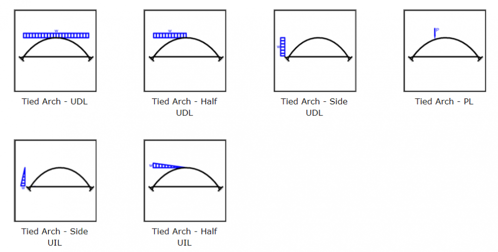


-
Insulated Concrete Load Bearing Wall Penals
Simple Structures replied to Mian Muhammad Aslam's topic in Concrete Design
Here are a few observations - i am not a user of ETABS, so my comments are of a general nature. 1. Shear walls have large lateral (wind, earthquake) forces that are transferred from the floor diaphragms down to the foundations. The connections between precast wall panel and floors/columns should be able to transfer (shear) load; This often is not possible unless reinforcement crosses through the insulation and connects the wall to the floor/column element. You cannot rely on four connectors at corners or pure friction of concrete to concrete. 2. For a 200mm (8") panel, one would require minimum 50mm (2") insulation to achieve any meaningful thermal benefit. This leaves two concrete biscuits of 75mm each. I m assuming theses are connected around the perimeter only? Ii there any connection of reinforcement (truss-like) between the panels with panel area? 3. I think the system may be ok for say 2-storey low rise building. 4. For modelling i would take 200mm - 50mm = 150mm thick panel. See what other learned colleagues say. -
Hi All, Structural Design is all about either knowing the subject, or knowing where to find the information needed to complete design! My Question to you all: In Pakistan what are the "essential design guides and information" you have handy on your desk and use all the time during your day to day structural design activities? Codes? Drawing Software; Analysis Software; Steel beam tables; Reinforcement data; Khanna's Civil Engineering handbook (for desi tips)? etc. Reason for question: It would be good to share and collate this information, with a view to developing CPD activities for Structural Engineers in Pakistan. Here is some of my list: Codes: Eurocodes; Units: Metric (as used by 95% of the world); AutoCAD & Revit (Drawing); ANSYS, MasterSeries and Robot (analysis software);Reinforcement Detailing Manual; Pakistan Manufacturers data on structural Steelwork and reinforcement; Structural Steelwork Designers Handbook; Reinforced Concrete Designers Handbook; Khanna's Civil Engineering Handbook (for design tips and a smile), and much more….. Please do share .... knowledge shared, is the glass half full approach for the betterment of our Structural Engineering Profession ...?
-
Is it in my head or is this forum too quite?
Simple Structures replied to ANStructs's topic in Shout Box
You are currently in the honeymoon period.... it wears off with time. -
Try this lecture link - it gives all info you need - http://web.engr.uky.edu/~gebland/CE 382/CE 382 PDF Lecture Slides/CE 382 L3 - System Laoding.pdf
-
Does Pakistani PE licence 'come in handy' in other countries?
Simple Structures replied to ANStructs's topic in Shout Box
@ANStructs Pakistani Structural Engineers need to take a lead on this. In Pakistan there is too much reliance on "government" or "governmental bodies" for everything. You should know how our politicians get to where they are, IK excepted, and what their motivation is. Let each one of the Pakistani Engineers make a contribution, and take a lead at local level, in their city or district - Organise structural engineer meetings, make presentations and share your experiences! Universities, their funding should be linked to research they publish. No other way. Hope to see you at the first such event later this year, hopefully in Islamabad .... nearest big city closet to my village ... Watch this space! -
Once you have the loading on the wall from its self weight, and slab its supporting above (check how many storeys, 1 or 2 or 3), and then apply this as a line load on your foundation or slab at ground floor level. 1. With light loading we would thicken the ground floor slab and distribute load thus, at 45 degrees, and ensure allowable bearing pressure is not exceeded; 2. For heavy loading you would provide a foundation below the wall, below the slab.

-
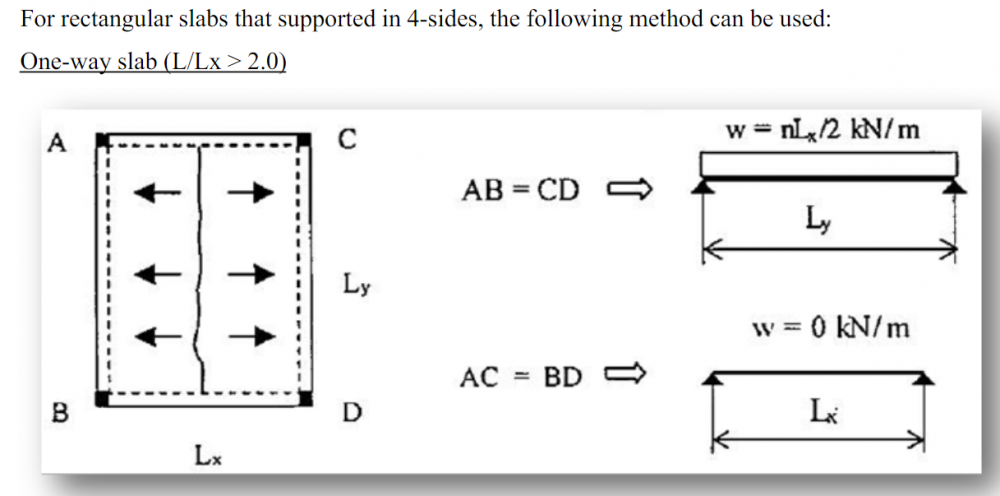
Tributary Area Method - The area of slab above supported by the wall. This is a little "trick' assignment I would give to a fresh graduate engineer - but a good example for you to understand the concept, of loads onto walls or columns from slabs they are supporting. In your case, the residential building has the "main load bearing" walls. These will support the slab above. The walls you have highlighted seem to be to be "minor" bathroom walls. If these 'minor walls' are built at the same time as the 'main walls', then the concrete slab will impose load on these too. If these walls are built afterwards, once the slab has cured and deflected, and the load is taken by the main walls then there will be very little nominal load on these walls - from deflection of the slab under super (finishes, furniture, people etc) loading. Also, in the plan you have shown the geometry of slab would mean that in majority of cases, the concrete slab would be spanning "one-way" and not "two-way". Nevertheless, see illustration below on how the load would distribute onto walls from such cases. Now using the same logic work out load on your slab. Does this help?

-
Does Pakistani PE licence 'come in handy' in other countries?
Simple Structures replied to ANStructs's topic in Shout Box
For example, there is lack of sharing of research between Pakistani universities, research which the Pakistan taxpayers have paid ... having spoken to a couple of profs, they tended to agree.... There are no platforms (SEPakistan excepted) for Engineers to share their experiences of practical work......? There are no regular publications of structural building design and construction papers ...? There are no field specialist’s knowledge harnessing and sharing platforms.......? The infrastructure for such knowledge sharing and practising is missing - everyone of us needs to take up the challenge to change things for the profession in PK.... 1. We require a PEC consensus of Pakistan's specific design codes - country specific design guides? Not an easy task. 2. PEC must consider having separate branches dedicated to each profession, to help each profession to blossom - civil, structural, electrical, chemical engineering etc....just like the rest of the world. 3. Universities funding should be linked to research papers published - just like everywhere else. Needs to talk to IK & HEC. 4. Formal PE examination system must be put in place for Engineers - we all need to contribute. 5. CPD activities must be developed and rolled out - we all need to contribute; 6. Maybe some of us Engineers on this platform need to do something as individuals too - hold courses or arrange conference on practical aspects related to structural engineering - I will now from today Insha'Allah set out to plan holding a course in Islamabad & Mirpur during 2020 (Covid-19 restrictions permitting) on a "practical structural engineering" topic ..... and will start preparing the course notes from today! 7. Let us all further the structural engineering profession in PK .... & yes, we can.... it depends on who and how many of us are up for the challenge. Apologies if this post is sounding like a political speech - I hope no forum rules have been transgressed by the content of this post. -
@abbaskhan2294 One book to reference on connection design is: Handbook of Structural Steelwork Connection Design and Details by Akbar R. Tamboli.
- 12 replies
-
- 1
-
-
- truss connection
- pin connection
- (and 1 more)
-
Does Pakistani PE licence 'come in handy' in other countries?
Simple Structures replied to ANStructs's topic in Shout Box
PE or Chartered Structural Engineer: As far as I can tell, there is no formal Structural Engineering Institution in Pakistan. Such Institution assess specific competencies of local Structural Engineers, and then promote them overseas. Pakistan Engineering Council registration is only formal requirement that I know of, and that is mostly based on having a civil engineering degree, the only the pre-requisite for registration as far as i can tell? In developed countries Structural Engineering Exams are taken after 5 years practical design and construction experience and these examinations can have pass rates of 35% - i.e. 35 of the 100 engineers taking the exam pass. In such cases, only Engineers with real practical design and construction knowledge experience become PE or Chartered. Such professional accreditation is then recognised internationally. Also, I am finding in Pakistan open knowledge sharing is done very reluctantly - don't know why 😞 -
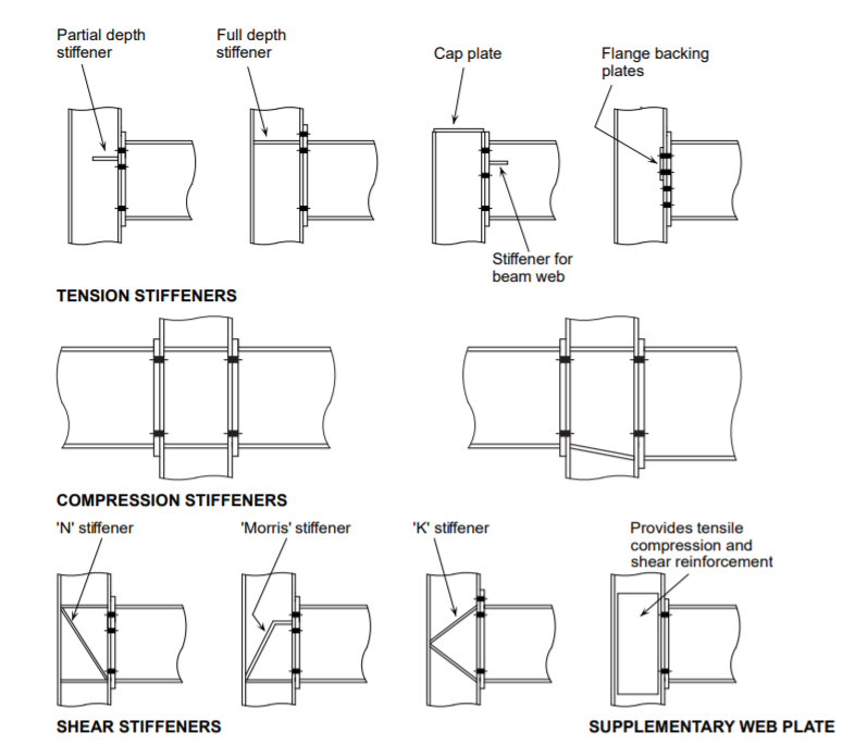
Full and Partial moment resistant connections in steel frame: First thing to note is that steel frame design is all about understanding and mastering joint behaviour and joint design!..... whilst selection of beam or column size is easy.... it’s the joints that determine how the frame will behave under vertical and later loading. Steel column to beam joints are characterised by "stiffness" (rigid joint, semi rigid or pinned) and "strength" (full, partial or pinned). For moment resisting frames the joints are MOSTLY "continuous or full moment resisting". As "semi-continuous or partial moment resisting" joints are discouraged as it relies on rotational stiffness of the joint. This is not easy to do, and thus most codes do not recommend it. I have previously in another post said that one connection that I may design for "partial fixity" is the column to foundation connection - only for lateral sway purposes. Please read that post. In such cases the column is provided with minimum of four bolts spread apart, to assist during erection of the column as first item of frame. With four bolts it will stand up under temporary case (as a cantilever till beams are fixed to it), and often the most onerous loading case. Here are pictorial examples of "full moment resistance connections in steel frames".... detail design of connection is an art. The connections require thick end plates, bolts with large lever arm, and cap and backing plates etc. Hope this helps the understanding the "moment resisting steel frame joint". By the way, I started my career as a structural steel welder, reinforcement steel fixer, then a draughtsman, then Engineer .... thus I have welded and erected many steel frames in my early years! The reason for mentioning this is that Structural Engineers, who have become engineers through gaining degrees and have missed out on practical skills, should make a habit of regularly visiting construction sites regularly, look at the details, talk to the trades men (or women) on site, and gain valuable experience from their see and hear….
- 12 replies
-
- 1
-

-
- truss connection
- pin connection
- (and 1 more)
-
6. Ooops… the question related to a truss connection... just to add, same applies to a truss end connection, where top chord and bottom chords are fixed to a column, the depth of truss (lever arm) the moment connection, and resistance to sway. 7 ...the internal connections, nodes in a truss are workshop welded, are pinned. …unless the truss is too big for transporting on a lorry, and then a bolted "splice connection" is provided to suit transport length to get the full truss length. These splice connections are bolted on the ground at the site location, and then the truss is lifted by crane into place (members also designed/checked for this temporary crane lifting forces!). 8. Finally remember, in a truss the loads in members in purely axial (compression or tension). 9. In a Vierendeel girder, where there are no diagonal members, then the vertical member and top and bottom chord connections are moment connection. But the site "splice" connection on the Vierendeel girder is also bolted.
- 12 replies
-
- 1
-
-
- truss connection
- pin connection
- (and 1 more)
-
Let’s consider a steel beam to steel column connection – to respond to your query: 1. The connection first needs to be designed for the Shear Force on beam end - this vertical force will dictate - number of bolts or length of weld. 2. I have designed a pin connection, with two members, being connected by a 75mm (3inch) diameter pin/bolt – a large single bolt and a gusset connection gave me the pin behaviour, and full rotation at the connection. Full rotation at the connections means you will get close to a "pure pin" as you can get. Such connections are often used for "special" architectural features structures. 3. For a beam connected to a column say, a 2-bolt connection would be considered as 'pin' connection; Even a 4-bolt connection would be considered a pin; The higher the shear, the higher the number of bolts. Still pin connection! 4. For a moment or fixed connection, the end plate on the beam will be thicker, will have welded stiffeners, on both end plate/beam, and on column web too! The forces are much higher, and rotation of join is restricted. If you have a building where no shear walls or X-bracing was allowed anywhere then you would design all beam/column connections as fixed "moment connections" - sized to suit the moment you obtained from your structural analysis. The moment connections provide the lateral sway resistance also in this case. 5. Welding in a quality-controlled workshop is good - welding on site, often overhead welding situation, requires special procedures and specially trained welders! In most developed countries there are special procedures for site welding followed by onsite weld testing - site welding is therefore avoided where possible.
- 12 replies
-
- 1
-
-
- truss connection
- pin connection
- (and 1 more)
-
Calculating Partition Wall Load on Slab
Simple Structures replied to Muhammad Munaf's topic in General Discussion
With "Initial structural design" and sizing I use these loads - these can be checked / verified further, if needed, at detail design. These figures always work. Loading should be generous at "initial design stage". These are the blanket UDL "dead loads" figures that I use, say for an office building design: Floor finish - screed/tiles : 1.8 kN/m2 ( 35psf); Ceiling and Services 0.5kN/m2 (10 psf); Lightweight partition system : 1.0kN/m2 (20 psf) Concrete block/brick partitions - 2.0kN/m2 (50 psf) - you can also check these as line loads at detail design is floor to ceiling heights are high, or lots of close blcok partitions exist. Over the design life of a building, say 50 years, the partition and finishes can change - design safe. -
Structural Plans for Famous Buildings
Simple Structures replied to hali's topic in General Discussion
Famous building plans - you can find some generic ones on the www .... just search. But structural critical technical details like thickness of floor plate, concrete and steel strengths, column size etc, key structural details may be difficult to ascertain? Older historic buildings were constructed with lots of redundancy, shorter spans and with inherent load sharing systems - hence have stood up for many many years. Your dedication and commitment to structural engineering is lauded! -
In addition, The links (stirrups) will need to be designed (sized) for both their normal "shear function" and also for "vertical tension" - on the links/stirrups from the slab "hanging" below them. Design links/stirrups as bars (also) in tension - reinforcement diameter may well increase in size.
-
*later should read *lateral
-
...carrying on this debate.... 14. The foundation is there to provide safe bearing pressure onto the soil below. This will have Horizontal and Vertical reactions - with Moment released. 15. With a concrete frame you transfer later loads from the sides of the building, into floor plate diaphragm and then down the shear wall into the ground. This later load converts to push-pull onto the foundation (resolving the moment). The foundation at this shear wall location sees maximum forces and is designed appropriately with the increased forces. 16. The stiffness of a column is very little compared to a wall - hence load is attracted to stiffness, the wall. 17. As we are all locked in our homes due to Covid 19 isolation, I suggest for your own peace of mind - run both analysis - with varying base restraints, check results, design foundations to suit and satisfy yourself. 18. Don't forget computer software is only an analysis tool, and practical engineering judgement is needed for safe and economic structures. 19. I do always carry out a quick design by hand, get a feel for the answers to be expected, and then move onto computer analysis. I am sharing my thoughts here to pass on my experience for the benefit of young structural engineers, the final decision is always the Design Engineer's!
- 20 replies
-
- 1
-
-
- pin support
- fixed ends
- (and 1 more)
-
Good question - I will respond using the same numbering as previous post – read that again - thus saving me repeating the same points again. It’s the "Hinge Detail" that you are asking about. 9. I have yet to meet an engineer who has detailed this connection in practice for concrete column in a building structure! Only place I have cross across true "pins" or "hinges" is in wooden and concrete arches. The proposed detail is not practicable for concrete fame buildings. 10. This is a very unpractical detail with very little, I would say zero, benefit. Could you construct a column like this, remove the formwork and leave it standing vertically as a cantilever, till the slab is cast? No. Therefore it’s not a buildable detail either. 11. To get a true "pin" or "hinge" with the illustration you have given to allow rotation, the connection would also require the dowel bars to be "de-bonded" and to work as true pin or hinge would require "crushing" of the reduced area of concrete, to activate the "hinge" and "pin". This then begs the question how the column compression load is transferred through the interface concrete. 12. There are no stirrups at the hinge in the detail. As hinge is supposed to move, the concrete cracks. Therefore, any water in the ground would penetrate the crack and corrode the reinforcement - inherent durability problem with the detail. 13. Let me think, the only location you could adopt the detail is when two cantilever beams meet, and the "hinge" detail is adopted to stop any relative (vertical stepping) at the detail. Ignore the book detail, indeed cross out the detail yourself from it, if you don’t want to bin the book...it’s not a really a practical detail. Forget it.
- 20 replies
-
- 2
-
-
- pin support
- fixed ends
- (and 1 more)
-
Diaphragm - Difference between Shell and Joint Diaphragms
Simple Structures replied to Rifat's topic in Software Issues
The Question is a little vague, and also difficult one at the same time. I am not an expert on finite element modelling but here are general thoughts to move the discussion along, based on my basic understanding. Firstly, here is my interpretation of question you have asked - You are referring to modelling the diaphragm (floor) and frame (columns and walls) for your computer analysis program input? 1. In a concrete frame building, one uses the floor slabs to act as diaphragms (deep beam analogy approach, where beam-depth is assumed width of slab, we then have tension and compression flanges/ chords etc) to transfer horizontal wind or notional force or earthquake loading to the core walls or shear walls, which in turn take it not the foundation and the ground. In this case, we detail the edges of slab with additional 'deep beam' reinforcement, and also design the connection between the slab and vertical elements (walls and columns) to transfer the load. Openings in the slab, floor plate shape all play a part in the way diaphragm will act. Also, a slab diaphragm can be designed by hand calculations using 'deep beam theory' approach! 2. Under horizontal wind or seismic loading, there will be a vertical element (column, wall) drift or sideways movement, and also side-way deflection of the slab, at mid span of slab 'length'' (along edge of slab). 3. Refer to the User Manual or commentary of the software you are using, look at its definition and input requirement of the two types of diaphragm discussed in your question. Some seismic codes also define - shell, rigid, flexible diaphragms etc. Rules and definition for each are given in the relevant codes. Span-to-depth ratios in the horizontal plane come into play here. 4. In an analysis I can make the diaphragm rigid (ignoring deformation) or model the in-plane stiffness as a shell diaphragm. In this case one will get slightly different results from the computer output, based on what assumptions we made in modelling stiffness. If no stiffness is inputted, then no output of force will be possible. 5. Therefore, putting it simply, the slab (diaphragm) is inputted in many analysis software as shell elements with defined nodes, and with defined parameters. Then where the frame (columns and walls) meet the slab elements, joint nodes are created, and these are checked and input with the relevant degrees of freedom and/or joint releases. Forces and moments can then be taken at these shell and joint nodes. 6. During modelling the diaphragm and walls are attached to the same mesh nodes, whilst diaphragm and column are attached to the same joint. 7. Finally, look at the Design Codes definition of the same & also your software User Manual, as a starting point to getting an answer to your query. I am not sure if I have answered the question asked by you, but hope I have at least moved the topic along, for other engineers to contribute further? -
Lateral load resistant of Stair ramp
Simple Structures replied to Aye Min Khaing's topic in Concrete Design
1. Design for gravity initially, then for axial loading (+/-) a part of a braced system. 2. Make slab / landing connection enough to allow for excessive deflection and reversal of loading, with some torsion. 3. Always put staircase inside core walls – i.e. rectangular concrete box - if you can. This allows better detailing and transfer loads via wall. 4. Most stairs in South Asia span between columns (i.e. corner connections), thin slabs with brick on top to make steps; Poor stair / column connection leads to failure in many cases. Also, quality of concrete is often poor. 5. Design stair as diagonal bracing subject to push-pull loads, with the vertical support member / column connection given greater attention; Hence best to have them spanning onto walls between column.... this then leads to "captive column" scenario. Design with full tension laps, with torsional provision in built. 6. Modelling of staircase in computer model will help give idea of behaviour, then you use your engineering judgement to improve the robustness of the staircase slab and its end connections. 7. Remember staircases are used for emergency evacuation following an earthquake, so should be designed a s "key element". Conclusion - a combination of modelling and engineering judgement helps - give the staircase slabs maximum attention - rest is often luck.