Simple Structures
-
Posts
103 -
Joined
-
Last visited
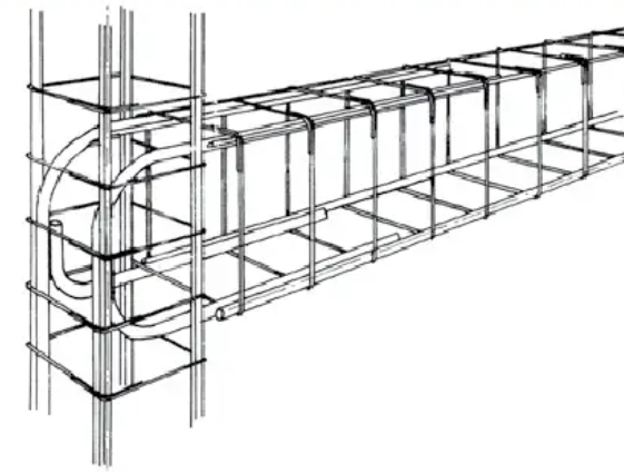
-
Days Won
41
Content Type
Profiles
Forums
Events
Everything posted by Simple Structures
-
Yes, you can use "fixed bases" in the analysis. There the bases have to be designed, ensuring no rotation, for "full fixty". The cost of such foundations in many such cases can be prohibitive! As said, I have only designed fixed bases for crane supporting industrial buildings. With fixed base performance, one is also relying a lot on "soil-structure" interaction, which is new debate and topic in itself .... not all structural engineers have sufficiently versed in geotechnical knowledge. Design safe, be safe.
- 20 replies
-
- 1
-

-
- pin support
- fixed ends
- (and 1 more)
-
@SMAQ 1. Let’s look at a simple single storey frame, with single bay, sitting on isolated pad foundations. The frame will be subject to VERTICAL gravity loading + HORIZONTAL wind loading. 2. At the top of the base there will be horizontal force from wind (as well as vertical load). For bearing capacity check you would convert that horizontal force to a moment (H x base depth) and then check ground bearing capacity is less than allowable. 3. In analysis, you put a pin joint at this location. (V, H but no moment). Vertical loads are fine; The sway (lateral displacement) of the frame will be determined by the column stiffness / inertia in that direction. As the base node is input as "pin", deflection will be higher. This will then be reduced, or brought into to allowable, by two things: a. by increasing the inertia (size) of the column. b. by providing a moment connection at the eaves, column/beam, joint location (zero M at base). The above two will enable you to bring the sway of the frame within allowable limits (say H/300 or H/400 etc). Where H is height of the frame. 4. In concrete frames base size and base connection are often determined by vertical load (& compression length of rebar into the base). The floors act as diaphragm and take all sway/lateral loading to the shear wall, stair or lift core walls, and transfer them into the ground. In these bases the forces are higher, there can even be uplift on one end of the base, and base design and reinforcement anchorage is more onerous. 5. You will now design/detail the column to pad base connection. 6. For a steel frame you would use 4-holding down bolts as a minimum for safe erection of column and design them for the compression load, and any tension generated by the horizontal case. 7. For a concrete frame you will have the column reinforcement going into the base, with full compression laps ...or tension laps if say it was braced bay in longitudinal direction. The rebar is always L-shaped and sits on the bottom reinforcement mat of the base. Say if the base was 750mm thick then the rebar will be 650mm+ben of say 250mm .... 900mm into the base. 8. now re-read my earlier post again about partial fixity always being present, but ignored in analysis, for a safer frame design etc. Does this help in understanding the practicalities of the column base connection?
- 20 replies
-
- 2
-
-
- pin support
- fixed ends
- (and 1 more)
-
1. "Captive Columns" are in fact start of as unrestrained (long) columns which then become "laterally restrained", by walls coming into the side of them, normally in one direction. They are therefore captive in one direction. 2. Under seismic loading, the column is subject to lateral - horizontal forces in BOTH direction - so for this directional force this column length & depth (in each direction) needs to be checked. 3. For direction into the building, where the column is clear full height, no lateral restraint: 10'/1.5' 4. For direction along the building perimeter frame: 6'/1.5' 5. It important that structural engineers look at BOTH structural & non-structural architectural walls, beams, coming into the 'side' of the column, and thus making the column captive - and design accordingly. 6. One way to overcome this is to have the architectural wall run past the face of the column on the outside. This will mean cantilevering the slab sufficiently to have the wall sitting on slab. Wall detailing and tying to column detail would be be considered carefully in this case. 7. This Captive or Short column always attract much higher proportion of lateral earthquake loading due to their modified slenderness/stiffness, and will therefore need to be designed AND detailed accordingly to avoid its failure.

-
You cannot generalise, as eccentricities can vary and heavily loaded beams at greater eccentricity, can generate significant bending moment in the column, and the increase the reinforcement (bar size or number) in the column; The column would need to be deigned for both axial and bending. There is no hard fast rule for this, each beam/column location needs to be looked at and decision made. A concrete frame can come in many configurations: 1. The floor plate say with 2-way spanning floor slab supported on beams in both direction; Here slab load (dead and imposed) is shared by all four beams; One beam being slightly eccentric would be less onerous; 2. The floor plate say with one-way spanning slab with beams in one direction only, would mean greater loading on the beams, greater reaction onto the column meaning, then eccentricity consideration is important; 3. Say you have 300mm thick 'flat-plate' or 'flat slab' then the slab load comes into the column, and eccentricities become less critical . In this situation assuming slab punching shear etc has been checked, eccentricity of slab loading becomes less critical. Where torsion occurs, say a beam going pas and connected to one face of the column, then the torsional moment - and torsion reinforcement - would need to be designed for. With the question being asked, I am assuming you are designing a simple structure, hence not too much to worry – but do talk to senior engineer in your office and take his/her view. In highly seismic areas the reinforcement continuity is more critical, and detailing for load/stress reversal is critical. My advise would be: (1) to close up the spacing of the shear links/stirrups closer to the column joint, half the spacing to what you have in middle of beam. Say if you have shear links at 300mm centre at the middle of the beam, then make them 150mm centres closer to the beam/column joint - for a length of say 1/8 span length from face (in both beam and column either side of joint) (2) Provide sufficient tension lap lengths (say 40 times bar diameter, as a rule of thumb) Talk to a senior engineer in your office for job specific consideration.
-
Most software nowadays inputs physical member sizes, i.e. column size and beam size, including centre lines. The analysis programme is therefore able to calculate any additional moment due to eccentricity. Also, in concrete frame buildings there is the slab, which is built into both beams and columns, and helps mitigate eccentricity. You can also cross check with a hand calculation knowing the eccentricity of loading - this hand calc check should assure you. Remember the beam width does not always match the column plan size - especially around the perimeter, where the edge beams may be set to align with the outer edge of column. Keep things simple. Remember In the old days there were no computers and all calculations were by hand!
-
Pin Connection an RC beam in SMF
Simple Structures replied to callmeismail's topic in Seismic Design
For the lateral loading analysis, each connection is modelled either as fixed or pinned; The structure should be modelled as detailed on the drawing and to be constructed on site. I would not exclude anything.... each member stiffness and joint rotation input has to be right. A frame should be modelled as it is. -
With ACI codes bottom bar must go into the support a min of 150mm; I know there are variations to this - For robustness of structure bottom bar MUST always go into the column/wall support. I always prefer to provide full anchorage of bottom reinforcing bar into support. In seismic regions there is always forces variations whereby +ve moments can become -ve under cyclic loading, and vice-versa - hence best to have a robust detail.... U-bar ideal other provide full anchorage of bottom bar into the support, ideal for cyclic loads. Therefore, ALWAYS detail bottom bar into support - beam into column same detail as previously suggested.

-
Design: You assume "pinned" for analysis. Detailing & Construction: You still detail the column for reinforcement to anchor fully into the base....with compression anchorage provision of rebar into base....hence partial fixity is always there.
- 20 replies
-
- 1
-
-
- pin support
- fixed ends
- (and 1 more)
-
A good question. No base is fully pinned or fully fixed! 1. Engineering judgements are needed for base fixity, and experienced engineer use this judgement to analyse, design AND detail the column/base connection. 2. Fixed based require large footings - uneconomical in most instances; also, very difficult to get full fixity with a pad bases once the base rotates under moment. Only piled foundations with thick pile caps may offer anything close to full fixity! 3. Sometimes (not common) column flexural stiffness (EI/L, 4EI/L, 3EI/L etc) is used to derive "partial fixity" for analysis purposes. Majority of column/base connections are inherently partially fixed - but in analysis this is ignored. 4. I have analysed buildings with pinned bases, and then re-analysed the same frame for serviceability wind deflection assuming 10-20% fixity! All an engineering judgement call. 5. Pinned bases are used as a matter of course for most designs of concrete frames. There are exceptions to this rule: (a) for portal frame type crane buildings require fixed bases to limit lateral sway of frame (H/400), and make sure crane does not come off the crane rails; (b) Multi storey steel frames often use ‘fixed bases’ to limit frame sway at bottom, and design foundations accordingly. 6. In Pakistan I would always assume pinned bases for analysis purposes (although 10-20% fixity will always be inherent e connection of column/base, which helps but should not be assumed in analysis). Although this leads to higher moment on columns between first and second floors, and hence lower column needs to be sized the same as column above. 7. With a ‘fixed base’ frame the lowest column will attract greater damage to lowest column/beams during an earthquake. seismic regions. With ‘pinned base’ less damage to the column would occur and more to the beam ...beams are easier to strengthen later then columns! 8. My Conclusion: Use pinned bases in rc frame upto say 5-6 storey high for analysis purposes. Note design is half the story, make sure you sketch the critical reinforcement connection details for the steel detailer & fixer too. Hope this helps?
- 20 replies
-
- 4
-

-
-
- pin support
- fixed ends
- (and 1 more)
-
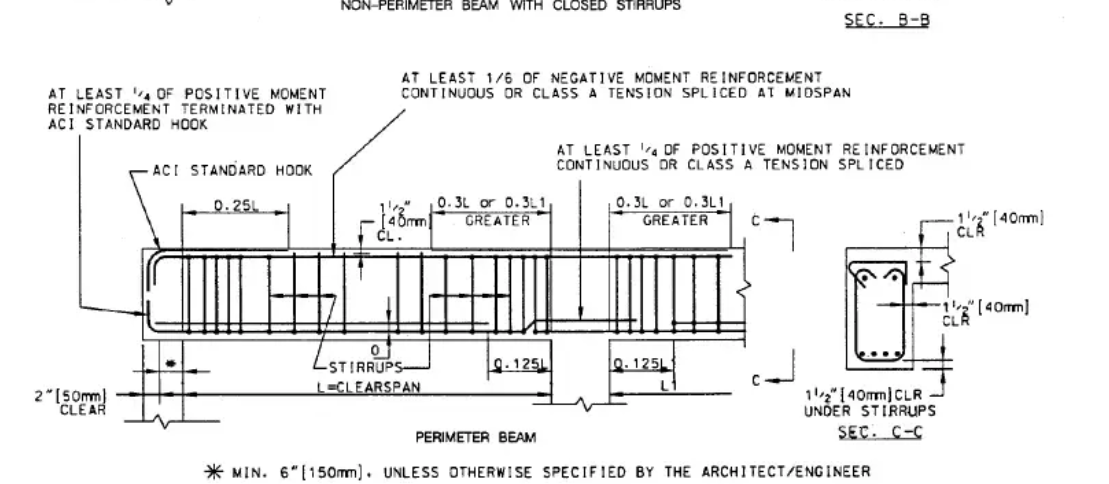
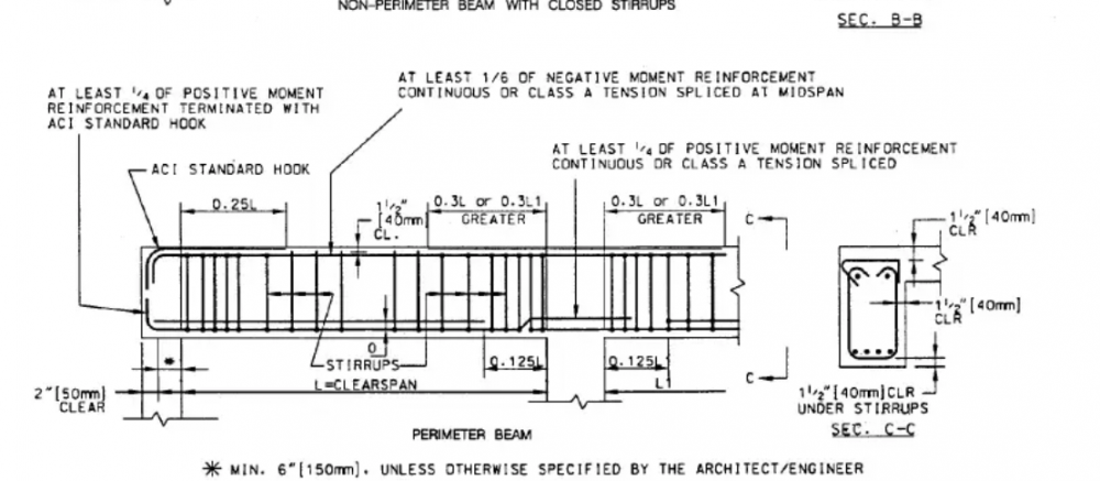
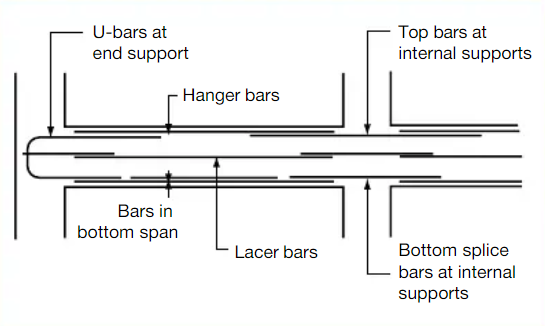
Based on European - Eurocode detailing rules (they are often more onerous - always safer than ACI code). 1. Bottom bars at support in beams and slabs should be bent into wall / columns support always. The key flexural bars are the top ones, and they should always bend into wall / column support to cater for the -ve hogging moment at supports! 2. If there is enough depth of slab, I prefer to use U-bars ...great for Pakistan where there are seismic factors etc. U-bars are ideal but not possible in all cases due to congestion of reinforcement. 3. For a safer approach, 50% of BOTTOM reinforcement should be taken through the external supports. All the top reinforcement to suit hogging moment. For Internal supports the requirement is for BOTTOM reinforcement is for 30% minimum of the reinforcement taken through the support. Therefore work to 50% in all cases for BOTTOM reinforcement for safer option. Curtailment of reinforcement rules to reflect bending moment, and lap length and minimum anchorage rules all apply when detailing. I prefer the some beam bars to be taken within 50mm of support face - just stop short - see second figure below. Hope this is helpful. Why don't we have a Pakistan Reinforcement Detailing Manual?
-
Pin Connection an RC beam in SMF
Simple Structures replied to callmeismail's topic in Seismic Design
1. A beam is fixed, where no rotation of beam column joint occurs, or pinned, where the beam is free to rotate. 2. In most RC detailing the top bar runs through the column, for robustness, so you always get some fixity. 3. Get a detailing manual (ACI detailing manual maybe) and see how a "true pin" can be detailed with rebar/reinforcement. .... a sort of intersection of the 'X' pin-points the "pin" location, putting it simply. -
vertical spring for Slab on grade - Calculation?
Simple Structures replied to Hasan009's topic in Software Issues
1. The geotechnical engineer - the soil specialist - should provide you the modulus of subgrade / elastic spring stiffness in his SI Report. Get in contact with him - this is the best and safest option. He is best placed to offer advice. 2. I have found that the geotechnical engineers often provide subgrade modulus to structural engineers by undertaking a CBR test, and then correlate the subgrade modulus to CBR value. They use a (0.6m x 0.6m, or) 1m x 1m plate for the test. The reason they don't do it that they would need to bring in heavy weights to do the test, hence they don't bother! I am sceptical of the CBR test as it only gives the strength of the soil in the near surface - In my view it does not give much of an information at depth. 3. In the absence of any information consult Bowles book on Foundation Analysis and Design I know has a table - which gives the different ranges of subgrade modulus based on various soil types. I don't have the book handy but recall it from distant past. If someone has the Bowles book handy, then they can help. -
looking for internship/training program
Simple Structures replied to shazeb mirza's topic in Member Introduction
@shazeb mirza You will need to apply for training job with Consulting Engineers and Contractors all over Pakistan, and possibly will need to travel to your job away from home.Get a good CV done, join PEC etc. I am trying to set up a consulting engineers office in either Mirpur or Jhelum during this year possibly, but that maybe some time away depending on how busy I am on other things during this year 2020. You can also email me your CV, for our file ...including your home town /village address - two referee names - I will keep this on file for when we are looking for people - BUT you must look for job elsewhere for the time being, don't wait for us. ecd.pakistan@gmail.com In the meantime, I would suggest there is no harm in you learning "AutoCAD & REVIT STRUCTURE" from youtube. -
Uplift Calcs - in response to @callmeismail query: 1m (3.3) = 10kN/m2 uplift (206psf) 2' = 2 x 62.4 = 124.8 psf 8' = 8 x 62.4 = 499 psf - so response to question is Yes.
-
Water pressure uplift - further thoughts @UmarMakhzumi approach is safe so go with it. Such technical deliberations, are also a matter of qualitative assessment by the Engineer. Engineers everywhere take a different approach to ground water level. Here we assume the water table (i.e. a possible perched water table) at 1m (3.3’) below ground level - for a conservative approach to basements uplift calculations, unless we have definitive information otherwise. If the structure is in water, or underwater, then the water level is taken as top tide level, or floor plain level. Do remember water density is 1000kg/cum (62.4 p/cuf) whilst concrete is 2500kg/cum (156 p/cuf) ... therefore 400mm thick concrete slab equals to buoyancy force from 1m (3.3') on water uplift - then add the factor of safety. Then there is also the 'permanent' dead weight of the structure above too. For shallow basements or structure, 2ft as you say, it may not be an issue provided there is sufficient dead concrete/structure weight? For un-factored loading - Factor of Safety against uplift, I use is 1.2 - some codes use 1.25. Most of the time dead wight of structure is well above uplift forces on shallow basements - there may be a need to control ground water pressures during construction of say basement slabs. Often water lowering (say pumping) methods are used during construction; Or you can use tension piles to hold the basement slab down against uplift for very deep basements.
-
Time for Pakistan Structural Engineering Profession (& PEC) to look at allowing Eurocodes use? I would like to advocate the use of EUROCODES in Pakistan for a number of reasons: 1. The Eurocodes covers all structural engineering design of elements, i.e. EC0 (basis of design), EC1 (loadings), EC2 (concrete), EC3 (steel), EC4 (composite steel/concrete), EC5 (timber), EC6 (masonry), EC7 (soils/geotechnical), EC8 (Earthquake), & EC9( (aluminium structures); These are adopted in 27 European countries, and also in Turkey, Malaysia, Hong Kong, Singapore etc. They should be used in conjunction with Pakistan Building Code which would be updated to include Pakistan National Determined Parameters. 2. American codes take an empirical approach, whilst Eurocodes are based on structural engineering theory and mechanics! Lot suited to teaching of theory approach in PK universities. I believe Canadian codes are closer to Eurocodes! 3. Pakistan would benefit from extensive research already in circulation on these codes and would be able to move forward in structural engineering t - and using the existing codes as a stepping stone to progress the country’s construction engineering academia and professionals progressing on with their own research etc. Whilst its not easy, I will attempt to lobby/inform the relevant authorities in Pakistan to look into this matter of Eurocodes design of structures in Pakistan. I would like to have the views of fellow structural engineers on the issue? Any thoughts on the matter?
-
DRAWING SOTWARE TOOLS - As a structural engineer I use – REVIT; NAVISWRKS, BIM. DALUS, TEKLA, ROBOT etc. REVIT is universally replacing AutoCAD for structural drawings on large projects - as the standard drawing tool. AutoCAD is used less and less outside Pakistan nowadays! REVIT offers the 3D working environment and is also very useful for quantities measurement and take-offs (volumes, tonnages etc) if needed as secondary use, primary use is drawings - In Europe (I presume the same is the case in USA?) - it’s all REVIT generated drawings for architecture, structure & MEP - as all projects MUST be BIM coordinated (for onsite clash detention and design management). REVIT is the background running programme that facilitates BIM (via Navisworks) - Building Information Modelling - when all disciplines' design information (i.e drawing model) in Revit (arch, str, mep, ffe) are brought together and confederated at the end of each working day - everyone working on the most up-to-date information & coordinated drawing model at the start of each working day. TEKLA is also used a lotfor structural steelwork detailing; inc reinforcement detailing - its is also an analysis tool. ROBOT is Autodesk’s own REVIT complimentary Analysis tool – Although REVIT drawing file can be brought into any analysis software – for structural analysis purposes. apart from ROBOT there are numerous other software for analysis and design. Then through DALUX viewer one can view the 2D drawing and 3D model views on a tablet whilst walking around site on a building project being constructed. The boundary between drawing technician (draftsman) and structural engineer is becoming greyer as knowledge of both drawing and analysis software is becoming a must for engineers - certainly overseas in Europe. Out of interest, are bigger Karachi, Lahore and Rawalpindi based practices using REVIT as their standard drawing tool nowadays or not?
-
Column Moment calculation by hand: 1. Which design code are you using - most likely ACI-318? 2. Then, get a good "structural design of elements" book to the same code - and follow the procedure set out in the book; 3. I would expect most universities in Pakistan would cover this in their "structural design" teaching lessons? 4. Or get a print out from a computer analysis programme and follow it by hand – learn the steps! Beam/column connection in top storey: Let’s understand that beam/column connection is truly 100% fixed, or 100% pinned (unless you put a proper hinge at the connection); So, designer must make the 'engineering judgement' on the matter. 4. Beam - Column connections are always continuous, as reinforcement/rebar will go from one into another, i.e. through the joint - so the degree of rotation assumed at the joint is the key; 5. The behaviour is somewhat between pinned (allows vertical shear transfer, but no moment, allows rotation) and fixed (where no rotation is allowed, or equal rotation is assumed in both members); Most computer software nowadays models the stiffness and rigidity of the connection, and determine the capacity accordingly. a sort of semi-rigid connection assumption. Also, very difficult to detail a "fully fixed moment connection" with reinforcement, unless you have haunches at the joint. 6. The key here is for the Structural Engineer - you the designer - to fully understand and appreciate the rebar detailing and lapping across the joint, the concrete cover etc. To be a good engineer you need to understand reinforcement detailing at the joint first! Visit a construction site and check the joint...sometimes there is some much reinforcement that you cannot get enough concrete around the bars for the bond! 7. Pinned, fixed and partial-fixed beam/column joint connections are easier to detail and design in a structural steelwork frame. Hope the above comments are useful.
-
Uplift on a Raft: Groundwater table fluctuates; However, site investigation companies can monitor GWL (piezometers are used for this purpose) over time and get a fair assessment of the water table. If you are founding on impermeable clay, then you can get a perched ground water table and pressure. In some countries with a lot of rain they assume GWL at 1m below ground level .... unlikely in majority of Pakistan where ground water levels/table are sinking (a major worry for future PK generations that we are not now addressing in our ignorance). Uplift Calc: Working to metric units: 2' above GWL = 0.6m; Uplift = 10x0.6= 6kN/sqm (can be resisted by 0.25m (equivalent to 10" thickness of concrete!) - hence uplift should not an issue! RAFT and building DEAD WEIGHT would be much greater! Say FoS= 1.1 against uplift and take Dead weight load factor as 0.9, for conservative design check. As @Ayesha said check fluctuation of Ground Water Table with the geotechnical engineer - geotechnical Engineers and their investigation report worth needs to be appreciated! There may be other practical construction related issues with constructing a raft under water - hence ground water level would need to be temporarily lowered - should not be an issue of the experienced builder who knows what he is doing.
-
A few further thoughts on ‘accidental torsion’, and how to compensate for it in structural design. I would agree with @BAZ comments above. There seems to be too much reliance on “computer software outputs” with little understanding of converting the analysis output to practical structural design details – I may be wrong. If for example the lateral forces resistance system, say lift core walls, are located bang on CENTRAL in the building, and no other shear walls are provided, then there will be global torsion that would be greater during an event, than if there are shear walls or cores on the four corners of a rectangular building. The structural elements (slabs, columns, walls etc) are then designed to cater for this torsion & any eccentricity. It is important that the SE appreciates that the .... 1. Plan geometry (layout) of the building; 2. Location and distribution of the lateral forces resisting system (i.e. shear walls, braced bays and cores) ...do matter in limiting earthquake damage. The use of infill blockwork walls as is common in PK. With no physical (vertical) shear tying/transfer of the infill panels to columns for force transmission, limited shear resistance is achieved, hence limited benefit. If infill panels are part of the lateral forces system, then they need to be detailed and tied to the column (never done?) .... the builder on site does not understand the structural robustness matters pertaining to infill panels ... he only gets paid for putting up more walls in a day!
-
Improve Bearing Capacity of Soil
Simple Structures replied to Muhammad Ameen Ali's topic in Concrete Design
1. Engineers need to be specific on soils - 'partly cohesive' can mean many things. Is there a site investigation report ? i.e have boreholes been undertaken to identify soil types etc below the excavated surface? One should always have a geotechnical / soils report for the site before undertaking any ground-works, such as compaction. Get a soils site investigation done first! Depth of boreholes ( i would suggest 5, 4 near corners and one in middle) below raft should be at least equal to width of raft; In this case as the overburden has been removed for sometime, the soil may have heaved (up) and this will settle as building load is applied! See option below with layer of 400mm small stone replacement; 2. After SI compaction options: 1, Dynamic compaction from height (could cause vibration to adjacent structures!); 2. Impact compaction special compaction adaption fixed to excavator; 3. rollers etc; 4. I would removed 400mm of top soil and put in stone compacted by roller, placed in 100mm layers; This will provide a good hard surface locally. 3. OK, water table is low...good... don't forget it will rain and if soil has too much clay you will get a perched water table around the basement! 4. Very difficult to judge if all future settlement will be taken out by compaction technique; use of raft footings will help limit this or the settlement will be uniform; 5. Basement walls will resist any lateral pressure - secant wall is only need for an excavation where site is tight and excavation slopes are not possible? 6. - 7. Raft ok 8....blank load on raft .... at column 0.8tsf (say 75kN/sqm) ... if columns are at say 6m centres then typical INTERNAL column load would be: 75x7x7 = 3675kN (or 0.8 x 21 x 21 = 350t) - for example! -
Improve Bearing Capacity of Soil
Simple Structures replied to Muhammad Ameen Ali's topic in Concrete Design
There are many factors that need to be considered here, to answer the post properly: 1. Type of soil - cohesive or non-cohesive? Techniques are different for both. 2. There are many techniques for improving soil bearing capacity. What techniques are readily available in the local market? 3. Water table level - impacts bearing capacity is sandy soils; 4. Is ground settlement your concern? 5. Working in metric units: kN & m; 0.75 tsf (80kN/sqm) to 1.8tsf (190kN/sqm): You must consider the "overburden removed". Two basements means (say 7-8m dig), therefore overburden (soil) removed would be 18kN/cum times say 7m = 126kn/sqm (1.3 ton per sq ft pressure removed). i.e. bearing pressure at the depth would be Pb+1.3tsf ...close to what you want. .... the key being water table or finding a low strength soil like "peat", in such or similar low strength ground cases ground improvement or piling solution would be needed - don’t undervalue the expertise of a geotechnical engineering specialist - consult them always! 6. Immediately after the dig protect the formation level surface by blinding with 75mm lean mix concrete or say 100mm of small stone gravel sub-base; 7. Raft footings - depending on thickness and stiffness, tend to then spread load over a large area, and would limit settlement etc. Not sure why a raft is needed in this case, as technically you have a 6-storey building - unless ground is very poor? 8. You have six/seven storey building - say superimposing a total load of 75kNsqm - 0.8ton per sq ft - (load obviously concentrated on column locations)! Hope this helps? -
Structural Design Codes in Pakistan? Can someone help me determine the "standard design codes" to be used in Pakistan for designing building structures; The Pakistan Building Code is a 'cut & paste' document with little practical guidance - hence superfluous I would say. Which codes do you use for 'structural design of elements’? 1. Wind Loading -? 2. Concrete design -? 3. Steelwork Design -? 4. Masonry design -? 5. Timber design -? 6. Geotechnical design -? 7. Earthquake design? & so on etc etc. There is the American Codes (ASCE, ACI, AISC, ADM) and European Codes (Eurocodes, EN, EC0, EC1, EC2 etc) for each of the above and more; Should Pakistan be adopting Eurocodes with the Turkey's Nationally Determined Parameters? Who is the custodian of the design codes ruling in Pakistan? PEC (another of the country's quango that is more interested in ticks box exercise, or am I wrong is that assumption) or is there another body that one can look to for guidance? Any feedback on the matter from learned Members would be most welcome.
-
Wind or Seismic design prefrence
Simple Structures replied to Waqar Saleem's topic in Seismic Design
The reason for "downgrading seismic grade" is so as not to alarm people! In Pakistan one prefers to ignore causes, and then react with much charitable sympathy and much fervour to the effects and consequences - that's the way it is here. Buildings are designed for: 1. Notional forces - to cater for design and construction inaccuracies and out of tolerance issues; 2. Wind loading - both building frame and facade components, The facade elements see much greater wind forces, especially at edges and corners; The wind forces come at the building for its full height and the building acting like a vertical cantilever... 3. Seismic. The most onerous design case no doubt, as the horizontal forces, building mass, member stiffnesses etc all play a part; The horizontal loading is applied at the base, and the mass of structure during earthquake motion above not in line with base! Therefore, Design for Seismic and check for wind too. As you also have a basement, the type of soil plays a big effect on both magnitude and location where the earthquake forces are applied to the frame. Understanding the soils structure interaction is key ... so speak to an experienced geotechnical engineer and also a senior structural engineer with seismic design experience - understand the soil structure interaction properly. Set and agree the Scheme Design Parameters first and agree with any checking authority (not easy in PK) before detail design on the computer ...which only gives you result for what you put in, rubbish in, rubbish out. -
Wind or Seismic design prefrence
Simple Structures replied to Waqar Saleem's topic in Seismic Design
Be careful - I am personally sceptical of the "Zone B" seismic classification for Islamabad. Therefore design robustly! With Seismic the forces are much much greater and the cyclic loading is more intense - there is no comparison in terms of magnitude between wind and earthquake force; Detailing of rc building reinforcement is also key.