-
Posts
49 -
Joined
-
Last visited
-
Days Won
3
Osama Anwar last won the day on July 31 2024
Osama Anwar had the most liked content!
Profile Information
-
Gender
Male
-
Location
Gujranwala
-
University
NUST
-
Employer
PRAXIS/IZAR
Recent Profile Visitors
3,297 profile views
Osama Anwar's Achievements
-
 Muhammad Faizan reacted to a post in a topic:
Guide for Response Spectrum Analysis
-
Assalaam o Alliakum everyone, I was wondering if someone could refer me some guide/learning material/book/video tutorials to design building by applying response spectrum analysis in ETABS. I am designing a building with extreme torsional irregularity. Seismic Design Category is D and T<3.5T_s so ELF can't be used. I have to apply some dynamic analysis. I know basics of RSA but I want a step-by-step guide to design structure using RSA in ETABs. Any help would be appreciated.
-
Is it not a standard practice in Pakistani Design Offices to use only earthquake forces for the calculation of drift? "Standard practice in the company" don't justify it as standard practice in Pakistani companies is to use EQ only?
- 24 replies
-
- wind story drift limits ubc
- drift
-
(and 1 more)
Tagged with:
-

Considering Purlin as a Lateral brace for Beam
Osama Anwar replied to Osama Anwar's topic in Steel Design
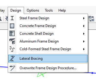
Moreover, what this lateral bracing option do? How to remove lateral bracing and when to apply lateral bracing? -
I am modeling some roof beams in SAP 2000. I wanted to know if I can assign lateral bracing to the top flange at the points where purlins are been attached to roof beam present in Design > Lateral Bracing option in SAP 2000? If not, why?
-
 Osama Anwar reacted to a post in a topic:
Lecture Notes/Comprehensive Textbook: Reinforced Concrete Design by Dr. Wael Hassan
-
Can we provide cross bracing in a moment resisting frame? Why can't I find any example?
-
 Badar (BAZ) reacted to a post in a topic:
Slab parameters for Open Grid Steel Flooring in ETABs
-

Slab parameters for Open Grid Steel Flooring in ETABs
Osama Anwar replied to Osama Anwar's topic in Seismic Design
I only want to investigate loads on beams and columns. Steel gratings panel are made up of bearing bars and intermediate bars. Bearing bar orientation is perpendicular to the span (c/c distance of adjacent beams) which varies from 2'-5' so I have to subdivide slab in such a way that beams are at 5' c/c in one direction. Length of grating may be equal to span or greater than span. I have not seen it, I know this from web surfing. I don't think it will be able to transfer moments. What do you think? I think it would act as one way. I wanted to model self weight through area element so I took mass of material as 0. I am using membrane with E almost equal to zero WITHOUT one way option. Will it do? Isn't deck for composites? If I am applying self loads through shell loads option i.e. unit weight equal to zero, setting the thickness won't matter. Right? Thanks for the great explanation. Much appreciated. Btw is there a steel frame in your profile picture? I was wondering which steel section we use as bracing in Pakistan? Angle or circular HSS or other? -

Slab parameters for Open Grid Steel Flooring in ETABs
Osama Anwar replied to Osama Anwar's topic in Seismic Design
Jazak Allah Umar bhai I had already considered the weight and taken clear span (5' in my case) from the online sources. I had also provided secondary and tertiary beams for this purpose as my primary beams span are very large (32' in one direction and 70' in other direction). What I understand is that I do not need to consider slab for this case, I just have to take loads and directly transfer them to beams. Jazak Allah for the reply Badar bhai It is class assignment. That's what assignment are for, to build basic understanding. I did that as lecturer told me to do so, but he did not go into much detail that is why I am asking. I have selected suitable steel grating for clear span of 5' using online catalogues and also corresponding weights, deflections are already catered for. I needed to know that can I model it as a slab that would automatically transfer loads to beams? Because assigning loads to hundreds of beams is a hectic job. That is also the reason I took stiffness equal to 0 by taking E=0. Should I model the slab or just transfer corresponding loads? -
Assalamu Alaikum Warahmatullahi Wabarakatuh I'm designing a Industrial building made up of steel which has a open grid steel flooring in one of its floor. I need to know what material properties I need to use and what slab parameter I need to select to model the open grid steel flooring in Etabs. The following site gives an idea about detailing of open grid steel flooring. Open Grid Steel Flooring – Structural Detailer In material properties I have taken Modulus of Elasticity as 0.00001. Also Specific Weight Density as 0 because I am applying its self weight as shell loads. And in Slab Property Data I have taken Modelling type as Shell-Thin and Type as Slab and Thickness 1". Is it alright or I need to change something to better mimic the reality?
-
 Ayesha reacted to a post in a topic:
Torsion Releases For Balconies
-
 Kamranullah reacted to a post in a topic:
Torsion Releases For Balconies
-
 Mazhar Amin reacted to a post in a topic:
How to apply line load on slabs?
-
 Aye Min Khaing reacted to a post in a topic:
Design system Rho and Sds
-
Jazak Allah for your Insights.
-
 Osama Anwar reacted to a post in a topic:
Max Percentage of steel in Columns
-
 Osama Anwar reacted to a post in a topic:
Max Percentage of steel in Columns
-
What about 0.85? Is it good?
-
 Osama Anwar reacted to a post in a topic:
Insertion/cardinal Points
-
You should not rely on Rho=1 and Sds=0.5. Rho can be taken 1 under many conditions. These are explained in ASCE 12.3.4. I have seen engineers taking rho=1 without any justification which is not right.
-
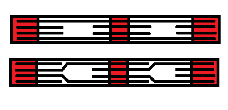
Assalaam o Alliakum Everyone! I have a beam in smrf with depth 2' and clear span 11'. As per ACI codes I can not provide lap within 2h from joint face. In my case that would be 2*2=4' so I can only provide lap within middle 3' (11-4'-4'=3'). But the problem is that lap splice length comes out to be almost 4.5'. I have 4 bars at beam ends and 2 bars in middle. Can I use following strategy to avoid lap splices. Red part is columns and lines represent top bars. Its a top view of beam. 2 beams are shown merely for understanding purpose in reality there are 8 beams. As far as I know bar length is 40' and 8 beams + columns equals to almost 99' so I have to provide 2 lap splices. Moreover I can not use mechanical splices because structure is being made in Pakistan and I have not seen such practice here.
-

Guidance with regard to the detailing of beam in seismic zone
Osama Anwar replied to Osama Anwar's topic in Seismic Design
Thanks for the reply I deal with imperial units L/4 is not equal to 2.75. Ln/4 is equal to 2.75. And Ln=11' not L=11'. My beam depth is 24" and L is 12.25" so 0.15*L+h = 0.15*12.25 + 24/12 = 3.875' As I said my beam depth is 24" and I am using #6 (0.75") bar. Hook length greater than 12db (12*0.75=8) does not contribute in holding concrete. I see no reason to increase my hook length unnecessarily. -
 Osama Anwar reacted to a post in a topic:
Guidance with regard to the detailing of beam in seismic zone
-

Guidance with regard to the detailing of beam in seismic zone
Osama Anwar replied to Osama Anwar's topic in Seismic Design
Thank you so much for the reply. ETABs neither considers full length (c/c) nor clear length while dividing the member into sections but average of both full length (c/c) and clear length like this My default is at Maximum Station Spacing and number of stations are 24. This means that ETABs divide each member in 24 parts and report values for each load combination. I have checked it. When we design our model ETABs give out 3 values for top and bottom reinforcement. I am interested to know that if members are being divided into 24 parts/sections/stations then each of the 3 values is being reported from highest of the 8 parts/sections/stations? i.e. left value is the highest values reported in the 8 parts/sections/stations on the left side and middle value is the highest values reported in the 8 parts/sections/stations located in the middle part of the member and right value is the highest values reported in the 8 parts/sections/stations located on the right side of the member. Right? -
 Osama Anwar reacted to a post in a topic:
Guidance with regard to the detailing of beam in seismic zone
-

Insertion Points and End Length Offsets in ETABs
Osama Anwar replied to Osama Anwar's topic in Concrete Design
Jazak Allah, my eccentricity is less than 9" (4.5") and beam lengths are at max 17.75'. Can you shed some light on how ETABs deal with insertion points and rigid links? I mean how these are different?


