Thila
-
Posts
8 -
Joined
-
Last visited
Thila's Achievements
")
Newbie (1/14)
0
Reputation
-
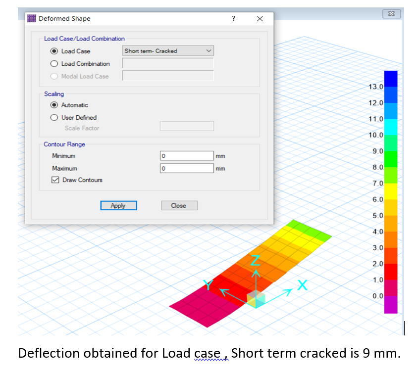
Short term (cracked) deflection for cantilever slab in SAFE
Thila replied to Thila's topic in Concrete Design
To satisfy the overturning and sliding, 1.0m x 1.2m footing size is enough. But just because of this deflection criteria, footing size and also the thickness of wall increases. Also is there any reference for short term (cracked ) limit horizontal displacement -
 Thila reacted to a post in a topic:
Formula for short term horizontal displacement
Thila reacted to a post in a topic:
Formula for short term horizontal displacement
-
Thila reacted to a post in a topic:
Formula for short term horizontal displacement
-
Thila reacted to a post in a topic:
Formula for short term horizontal displacement
-
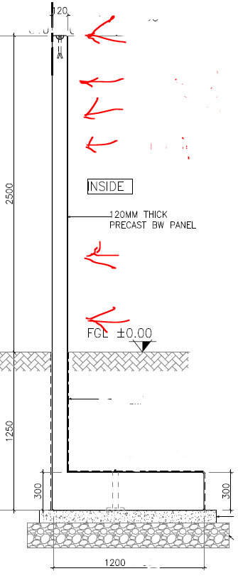
Ok. Thank you. But how can we ignore the soil fill load above the footing? How should we consider in calculating deflection. If I consider only the wind and active pressure, deflection grows higher. Footing size and thickness of boundary wall also increases. To satisfy the overturning and sliding, 1.0m x 1.2m footing size is enough. But just because of this deflection criteria, footing size and also the thickness of wall increases. The below is link is related to the same discussion. FYI https://www.sepakistan.com/topic/3126-short-term-cracked-deflection-for-cantilever-slab-in-safe/?tab=comments#comment-10203
-
Short term (cracked) deflection for cantilever slab in SAFE
Thila replied to Thila's topic in Concrete Design
Thank you. But is this correct concept to check the boundary wall deflection in this way without considering the soil load above footing. -
Thila reacted to a post in a topic:
Short term (cracked) deflection for cantilever slab in SAFE
-
Thank you. Can I consider pinned support at the earth top level as below?? I am modeling the same in SAFE too.
-
Thila reacted to a post in a topic:
Short term (cracked) deflection for cantilever slab in SAFE
-
Short term (cracked) deflection for cantilever slab in SAFE
Thila replied to Thila's topic in Concrete Design
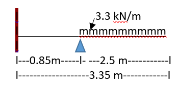
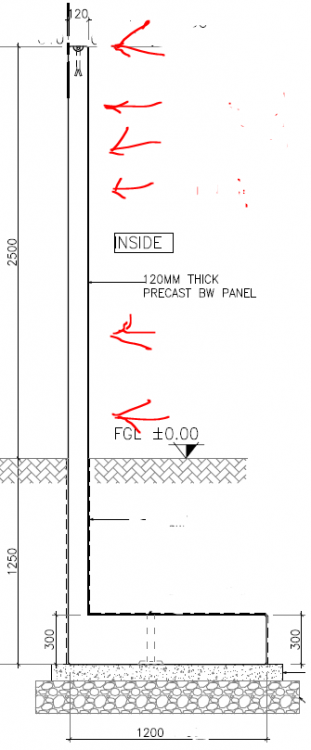
Hi, Thank you for your response. Self weight is ignored since calculation only for wind load. Manual calculations are as follows: l 1.1 kN/m l________________mmmmmmmmmmmmm l l---0.85m-----l- ---2.5 m--------------l l-------------------3.35 m-------------l B = 1000 mm D = 120mm Ig = 1000 x 1203 / 12 = 144x106 mm4 n = Es/Ec = 200000/ 26587 = 7.52 Fr = 0.62 SQRT (32) = 3.56 N/mm2 Yt = 120/2 = 60 mm Mcr = Fr*Ig/ yt = 3.56 *144x106 / 60 = 8.544 kNm Ma = 5.775 kNm Ma/Mcr <1, Hence Ie = Ig Deflection = w (uniformly distributed) *l3 / 8*E*Ig w = 1.1 kN/m = 1.1 n/mm loaded length = 2500 mm total length = 3350 mm E = 26587 N/ mm2 Ig = 144 x 106 mm4 Deflection = 1.1 * 3500*3500* 3500 / 8 * 26587 * 144x 106 = 0.0015 mm I posted the SAFE model snapshot also for your review.


-
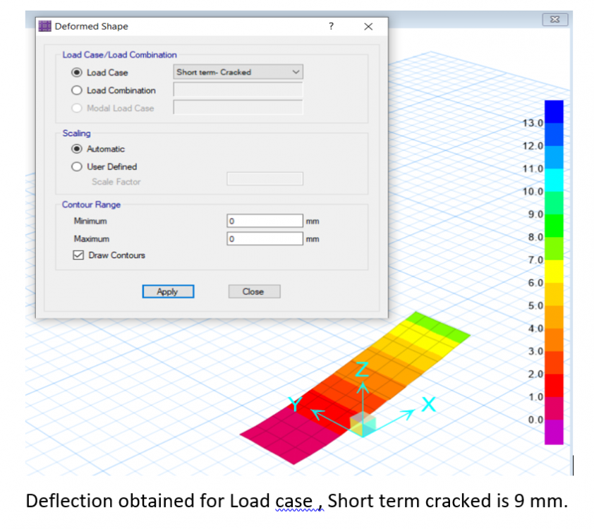
Hi All, How to perform analysis to check Short term (cracked) deflection for cantilever in SAFE model? I have to check for wind load alone. I entered "0" for material unit weight, since i consider only wind pressure. Also in Load case option, I selected "Non- LInear (cracked)" alone. I applied wind pressure of 1.1 kn/m2 for 2.5 m length of slab whereas the total length of slab is 3.5 m. Kindly find attached for geometry. Is this the right approach? why am I getting different result comparing to manual calculation? I have attached the SAFE model too. se-SAFE- defl chk.$sf se-SAFE- defl chk.FDB


-
Thank you for your response. . Can I take “Ig” instead “Ie”, if Mservice /Mcracking <1, .Because, Ms is not exceeded the cracking moment. Also , kindly review the calculation below. If it is not correct, kindly guide me. Thank you This is cantilever wall rests in eccentric footing, subjected to wind. The calculation is considering wind load only. kindly find attached for sketch l 1.1 kN/m l_________________mmmmmmmmmmmm l 0.85m 2.5m l----------------l----------------------l B = 1000 mm (taken per meter width) D = 120mm (thickness of wall) Ig = 1000 x 1203 / 12 = 144x106 mm4 n = Es/Ec = 200000/ 26587 = 7.52 Fr = 0.62 SQRT (32) = 3.56 N/mm2 Yt = 120/2 = 60 mm Mcr = Fr*Ig/ yt = 3.56 *144x106 / 60 = 8.544 kNm Ma = 5.775 kNm Ma/Mcr <1, Hence Ie = Ig Deflection = w (uniformly distributed) *l4 / 8*E*Ig w = 1.1 kN/m = 1.1 n/mm loaded length = 2500 mm total length = 3350 mm E = 26587 n/ mm2 Ig = 144 x 106 mm4 Deflection = 1.1 * 2500*2500* 2500*3350 / 8 * 26587 * 144x 106 = 1.88 mm

-
Thila reacted to a post in a topic:
Formula for short term horizontal displacement
-
Hi All,How to calculate the short term horizontal displacement (with adopting cracked section of the concrete) on free standing wall with eccentric footing at bottom, which is subjected to wind pressure alone. This is same as calculating torque of cantilever wall. This is a plot boundary wall with eccentric footing. Thank you