Muhammad SAqib shah
-
Posts
10 -
Joined
-
Last visited
Muhammad SAqib shah's Achievements
")


-
 Muhammad SAqib shah reacted to a post in a topic:
Roof truss deign , member length?
Muhammad SAqib shah reacted to a post in a topic:
Roof truss deign , member length?
-
Muhammad SAqib shah reacted to a post in a topic:
Roof truss deign , member length?
-
Modal Mass Participation
Muhammad SAqib shah replied to Muhammad SAqib shah's topic in Seismic Design
thanks sir -
Roof truss deign , member length?
Muhammad SAqib shah replied to Muhammad SAqib shah's topic in Seismic Design
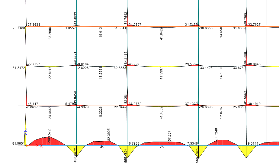
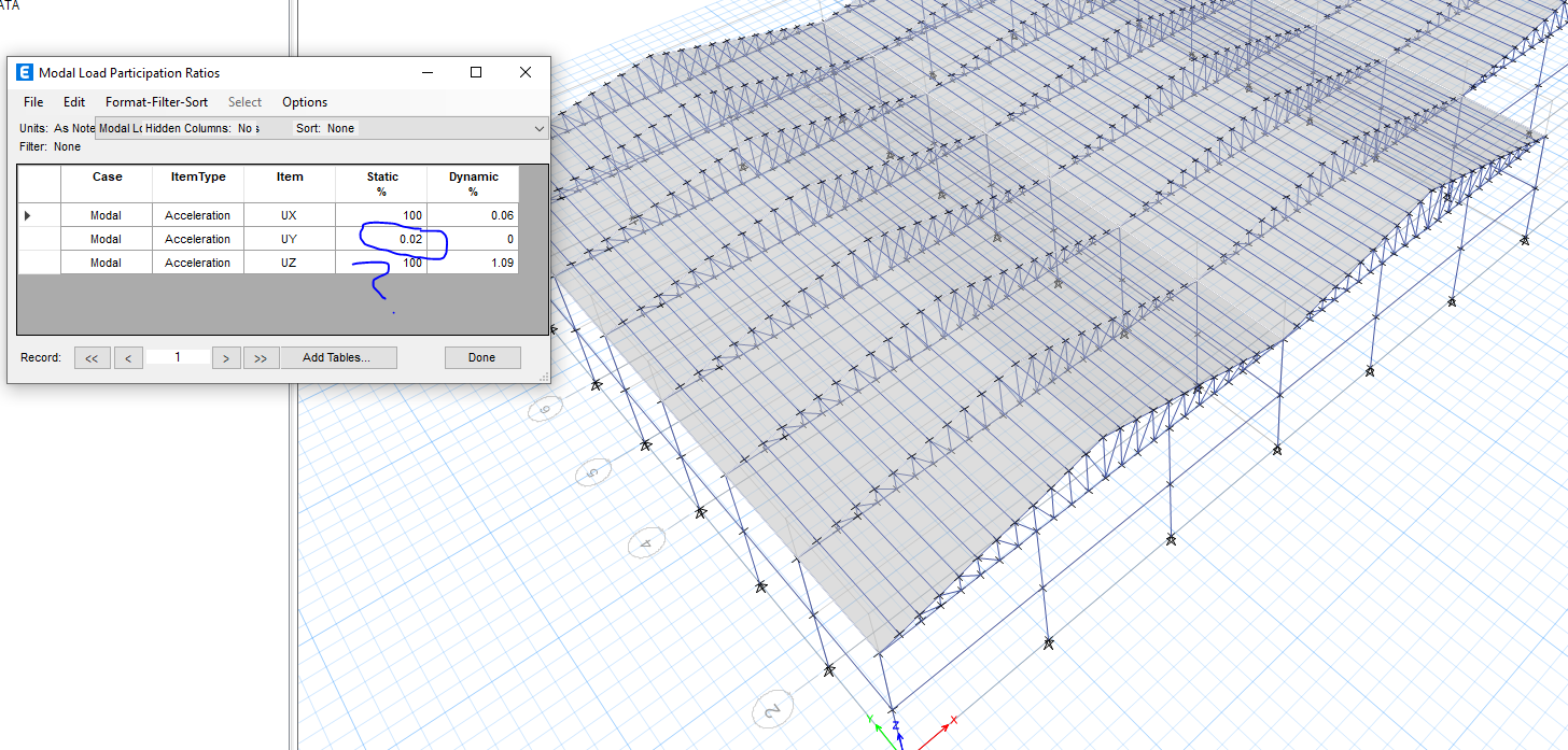
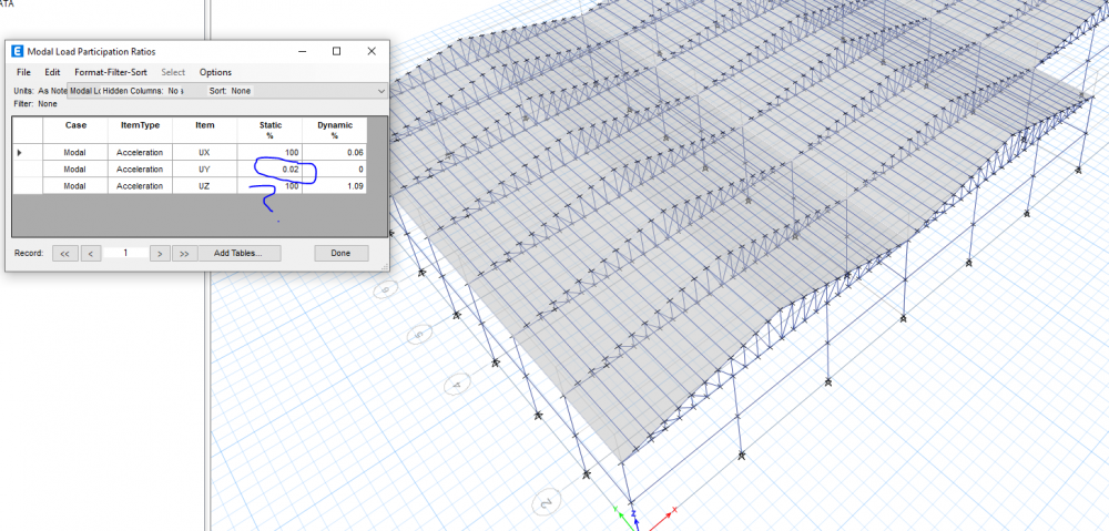
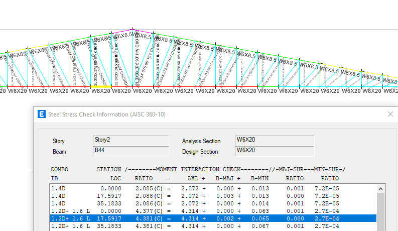
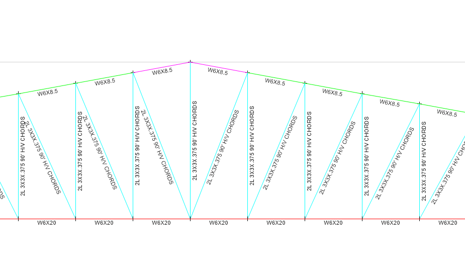
dear sir at this point the truss stresses changes from tension to compression ,this member has almost no stress thats why the diagram is small, any way the prob is some how fixed now there is another big problem , MODAL MASS PARTICIPATION IN x,Z DIRECTION IS =100 % BUT FOR Y DIR IT IS .46 , CAN YOU ENLIGHTEN ME ON THAT PLEASE
-
can any one explain the reason for this ? my modal load participation is Y direction in negligible .
-
Roof truss deign , member length?
Muhammad SAqib shah replied to Muhammad SAqib shah's topic in Seismic Design
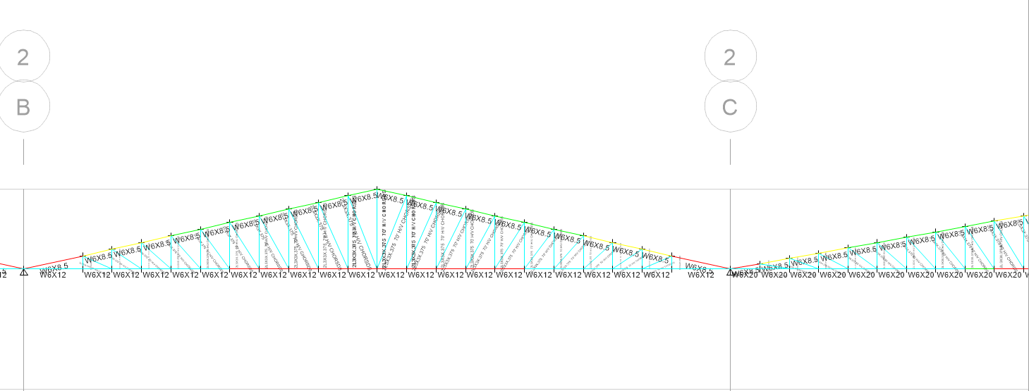
1)Etabs gives you the reason in its design report; it is clear that your member are failing in compression. reply = the bottom member should be tension member ?? no ? , why is it in compression ?? 2)There should be a node. reply = sir can you elaborate your point ? you mean the truss should be divided into segments ? 3) sir no segment is missing , you can check in other pix. -
hi guys hope you all are fine , coming to the point , i have been modelling trusses for a factory building in ETABS 19 ,details of which are attached , span= 90 feet , dist b/w two adjacent trusses is 18 ' horizontal /vertical chords =2L 2.5"x2.5"x3/8" (double angle) Top chord w-sec 6x8.5 bottom chord w-section =6x20 CGI sheet with 20 psf load on top. 1) the middle portion of the bottom chord is failing i dont know the reason for that ? i have released the moment for each and every joint in the trusses , 2) should the top chord and bottom chord be 1 member or divided at each intersection with the h/v chords ?? 3) the behaviour of the truss is not ok at the mid section , as it should be tension rather than compression , thanks very much in advance , cheers


-
Muhammad SAqib shah reacted to a post in a topic:
Raft Design For A 2 Basement+G+24 Story Building
-
Muhammad SAqib shah reacted to a post in a topic:
Minimum Thickness Of Footing
-
Muhammad SAqib shah reacted to a post in a topic:
Minimum Thickness Of Footing
-
Muhammad SAqib shah reacted to a post in a topic:
Spring Support- Modulus Of Subgrade Reaction
-
Muhammad SAqib shah reacted to a post in a topic:
High Soil / Bearing Pressure under Raft
-
Muhammad SAqib shah reacted to a post in a topic:
Raft Edges and Corners Overstressed
-
Muhammad SAqib shah reacted to a post in a topic:
Raft design
-
1) i want toAssign soil springs as i want to do the analysis in ETABS so what should be the value of Area springs for .6tone/sqft baring capacity ?? Raft Area = 120ft x 35 ft 2)There is always a Punching failure when columns are located along the edges of raft. Yet it's quite a common practice to provide columns along the edges of raft. How such rafts are designed? I am facing the same problem here. (fig-2) thanks

-
RAFT Design (Variable Thickness) SAFE 2016
Muhammad SAqib shah replied to Nabeel Sheikh's topic in Foundation Design
did you find yours answers ? having same problem. -
Muhammad SAqib shah reacted to a post in a topic:
RAFT Design (Variable Thickness) SAFE 2016
-
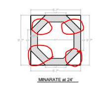
hel0o guys , 1) i am designing a minaret of 40 Feet height as wall sections (shear wall ) / is this practice correct ? 12'x12' Minaret. (square section) 2)from 0 to 20 ' it is square square , then from 20 to 40 ' it is circular , now the problem is the circular portion does not fit well over the square portion (RED CIRCLES are in air )how do we connect the two sections for safe load transfer ? how to do the detailing and do i need to provide a beam or sbal where the sections meet ? thanks in advance
-
what modifications specifically ? can you please elaborate ?
-
hel0o, i need an expert openion as i a, designing a raft foundation for 8 story building , 1 ) i have provided a deep beam in the raft foundation , below the columns(column strip) , which is 48"x36 " (24" raft+ reamaining 24" beam ) and in the middle strip the raft is 24 " see attached (Fig111) , is this practice alright to make the design economical ? column size 24x24 secondly what if i shift the raft to the top of foundation beam and , or in other words move the beams 24" below the raft which is more suitable for clayey soil? 2) i want to assign soil springs as i want to do the analysis in ETABS so what should be the value of Area springs for .6tone/sqft ?? 3) when i preform the analysis in SAFE (fig 222)t gives no results for column punching ? why is this so ? 4)why dosen't SAFE provide punching data for shear walls ? 4 ) My plot area is limited so the columns are on the edge of the raft ,is this ok ? thanks in advance