Wajahat Latif
-
Posts
21 -
Joined
-
Last visited
-
Days Won
1
Content Type
Profiles
Forums
Events
Everything posted by Wajahat Latif
-
Dual System Modeled as Sway/Non-Sway?
Wajahat Latif replied to Wajahat Latif's topic in Concrete Design
I agree with your observations. The 'sway moment' is amplified by P-Delta considerations, whether the frame is sway or non-sway and whether the column is slender or not. Regarding your following statement: I think the non-sway factor (catering for deformations between the member ends, i.e., P_smallDelta effects) would be computed in both non-sway and sway cases. No? In non-sway frames, only non-sway factor needs to be applied. However, since we're doing a P-Delta analysis, the sway factor is also inherently present. Similarly, in sway cases, both sway and non-sway factors need to be applied. So, in essence, ETabs is applying both sway and non-sway factors for all kinds of framing. As you've pointed out in the post you shared, as per code the moment magnification should not be applied for short columns, i.e., they can be designed on first order moments. However, given the above discussion, it seems these amplifications are being applied regardless if the column is short or slender. Now, I just noticed that the non-sway moment factor in "Concrete Frame Design Overwrites" is by default set as 1. We would need to set it to 0 for the program to compute this itself for each member for each load combination (screenshot attached). I suppose if we're confident that our columns are non-slender, then we can avoid the non-sway factor by keeping this as 1. The sway factor would still be applied via P-Delta.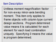
-
Dual System Modeled as Sway/Non-Sway?
Wajahat Latif replied to Wajahat Latif's topic in Concrete Design
Thanks. I agree with your points. I was running into a problem with a couple of columns in a dual system building. Based on the ACI 318-19 criteria of slenderness effects (Section 6.2.5), these columns are classified as slender in a sway frame but non-slender in a non-sway frame (based on the different slenderness limits for sway and non-sway frames in this section). When they're behaving slender, the ACI check mentioned in Section 6.2.5.3 (i.e, second order moments < 1.4 * first order moments, screenshot attached) should be applied. For my case, these columns are failing this check. However, I know from manual calculation that this is a non-sway frame and the columns are infact non-slender, therefore, this check can be ignored. In ETabs 19, this check is applied whether the framing type is sway or non-sway (columns fail this check in both cases). This makes me wonder, does ETabs perform all slender column checks and calculations regardless of whether the column is slender or not? Any idea how ETabs checks column slenderness?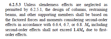
-
Hi all, wanted your take on the following. Columns in a dual system (shear walls + IMRF) behave as non-sway since the shear walls provide bracing for the moment resisting frame (ACI 318-19, 6.2.5). When this system is modeled in ETabs, should we select 'Sway Intermediate' or 'Non-sway' framing type in 'concrete design overwrites'? I believe the important IMRF checks of ACI chapter 18 would get ignored if we select 'non-sway'. An IMRF system on its own is designed to have an inherent ductility to resist seismic forces through sway action. Thanks.
-
Stiffness Modifiers for Pick Up Columns
Wajahat Latif replied to Wajahat Latif's topic in Concrete Design
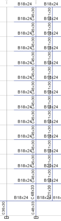
Okay. Hooks provided at the top-most and bottom-most ends of the column can be omitted. What about the intermediate story-level beam-column connections (referring to the circled region in the attached diagram)? Column bars are continuous here. Should we discontinue the column bars?
-
Stiffness Modifiers for Pick Up Columns
Wajahat Latif replied to Wajahat Latif's topic in Concrete Design
Here is the pick up column modeled in Etabs. To ensure this in the field, we would need to provide a pin-connection detail, correct? A mesnager hinge would probably do. Do you have any details on that? Have you seen that in any project? Thanks.
-
Stiffness Modifiers for Pick Up Columns
Wajahat Latif replied to Wajahat Latif's topic in Concrete Design
Thanks. That makes sense. I guess in my case, since the pick-up columns are also connected to the slab-level beams, I should probably provide the same modifiers as the rest of the columns. That's a good point. I'll see if I can find something in ACI. If you come across any such requirement, would be great if you can share it here. Thanks! One more question, what support conditions do you recommend providing for pick up columns? It's my understanding that no support restraint should be provided. -
I don't think this core wall will participate in lateral resistance since its not connected to the slab. For that reason, I think it shouldn't be modeled.
-
The code describes the dual system requirement as follows: "The moment resisting frames shall be designed to independently resist at least 25 % of the design base shear" According to this, your building qualifies as a dual system if the moment frame can resist 25% or more of the lateral forces. If your columns are taking 60% of the base shear and the shear walls are taking the remaining 40%, the building system still qualifies as a dual system. The actual base shear distribution between the columns and walls in your building will just depend on the number, type and arrangement of lateral resisting members in your building. The process of checking this in etabs that I mentioned above basically ensures that your columns are strong enough to resist at least 25% of the base shear.
-
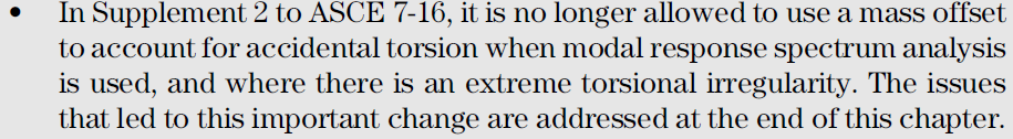
This topic troubled me a lot the last few months so I came across this post while doing my research. A quick update to the consideration of accidental torsion effects in RSA: the dynamic mass shifting procedure has been prohibited by Supplement # 2 to ASCE 7-16. Latest research found that buildings designed with this procedure were more susceptible to collapse. Now we're only left with the static method of accounting for accidental torsional effects in RSA (including amplification). To accomplish this in ETabs, we can find the amplified eccentricities along both X and Y axes from the regular ELF analysis. These amplified eccentricities are input in the RS-X and RS-Y load cases respectively. I confirmed this approach with Dr. Justin Marshall, the co-author of "Guide to Seismic Provisions of ASCE 7-16", and Engr. Aung, Director AIT Solutions. As WR-1 said, Etabs (link) will obtain accidental torsional moments from story forces obtained from the combined RSA, then add these forces to the combined RSA results. This is the procedure prescribed in the "Guide to Seismic Provisions of ASCE 7-16" as well, snippet attached. Omission of consideration of amplified accidental torsional effects in RSA results in very weak designs, and this is prescribed in both ASCE and UBC-97. Note: the dynamic mass shifting analysis is still applicable for linear response history analysis. However, for response spectrum analysis it is prohibited.

-
Hi, I need to provide pick up columns to support the landing beam of staircase. The story-level beams will also rest on these columns. The stiffness modifiers prescribed for columns by ACI is 0.7. I was wondering if I can reduce that to (say) 0.35 or less, since I don't want these columns to participate in resisting bending moments as much as the 'actual' columns. Note that their primary purpose was to support the staircase landing beam, so designing them on gravity only load should be fine? Also, any thoughts on providing a pick up shear wall with f12 stiffness modifier = 0.0001 i.e. not letting it participate in lateral shear resistance? Thanks. Best, Wajahat
-
Hi Arslan, just browsing through your posts. You might already have the answer to this. To check if the columns are able to resist atleast 25% of the lateral force, you should do the following: - Go to Mass Source and change the factors to 0.25 instead of 1. This would reduce the seismic base shear to 25%. - Change your shear wall f12 modifier to nearly 0, i.e. 0.0001. This would mean that your shear walls will not resist any lateral forces. That is, all the lateral force will be resisted by columns only. - Check if your columns are able to resist the lateral loads. If reinforcement in your columns is not exceeding 4%, you're good. - I would save this as a separate model and provide the maximum reinforcement in columns from this model and the original one.
-
Hi Arslan, I just came across this and since its a very old post you might already have your answers. But just to share my two cents, we should check the torsional irregularity against story drifts. However, we should calculate the amplification factor "Ax" based on story displacements. There are instances where you have torsional irregularity along an axis in a building (checked against story drifts) but your amplification factor is less than 1 (checked against story displacements), so you don't need to apply it. Its still important to check whether torsional irregularity exists along both axes or not to determine whether we need to consider orthogonal effects in our load combinations. I'm attaching an excerpt from "Guide to the Seismic Load Provisions of ASCE 7-16" to clarify the point about checking torsional irregularity and calculating Ax against story drifts and displacements respectively. This applies to UBC 97 as well. Both options would give you same results if you have a single diaphragm per story.

-
Ubc Seismic Drift Limits
Wajahat Latif replied to UmarMakhzumi's topic in Journal/ Articles/ Tutorials
Thanks for your response Umar. This was helpful. I suppose if we're using the fundamental time period to calculate drifts, they are almost never a problem. This is what I'm doing now. -
Multi-tower building with common podium in Etabs
Wajahat Latif replied to Wajahat Latif's topic in Seismic Design
Thanks. No I haven't studied at AIT. I attended his online lecture on 8th April that was advertised on AIT Solution's facebook page. Attaching the poster here.
-
Multi-tower building with common podium in Etabs
Wajahat Latif replied to Wajahat Latif's topic in Seismic Design
I emailed him. I'm yet to implement this since the building I'm working on no longer shares a common podium now; an expansion joint has been provided. However, in reference to making two sets of response spectrum cases (for both towers), I didn't find any option in Etabs where we could explicitly do that. I suppose this only means that after we create 4 regular RS cases (RSX-T1, RSY-T1 and RSX-T2, RSY-T2), we scale RSX-T1, RSY-T1 to match the manually calculated base shear for tower 1 and design this tower against these load cases. Similarly, we do the same for tower 2 by scaling (against tower 2 base shear) and designing against RSX-T2 and RSY-T2. What do you think? -
Multi-tower building with common podium in Etabs
Wajahat Latif replied to Wajahat Latif's topic in Seismic Design
Here is a response that I received from Engr. Aung, Director AIT Solutions. Sharing for everyone's knowledge. "You can consider the podium, Tower 1 and Tower 2 to be three different "towers", using multiple towers option. T3 is podium (Foundation to 3rd floor), T1 and T2 are Tower 1 and 2, starting from 4th floor to roof. However, it is suggested NOT to use ELF base shear from analysis if you have multiple towers in the model. Normally, ELF base shear for each tower above the podium is calculated manually for scaling purpose only. To determine the base shear for scaling of two towers resting on a common podium, it is suggested to compute the design base shear of each tower above the podium (using weight of tower above podium) based on code-specified equations manually. Then, scale the base shear of each tower above the podium in a 2-tower combined model in different response spectrum cases. You will have two sets of response spectrum cases: RSX-T1 and RSY-T1; RSX-T2 and RSY-T2. Use 2-tower combined model to design each tower with corresponding response spectrum cases. For podium design, you may use the envelope of those cases. For application of wind load in multiple towers, it is suggested to turn on "Allow multiple towers" in the Option menu and assign the diaphragm names separately for each tower. If the story height of each story is different between two towers, it is suggested to crosscheck the wind base shear of each tower above the podium with manual calculated results. It is okay to connect two towers on a common podium. It is suggested to check the in-plane forces in podium diaphragm due to movement of towers under lateral loads. If the seismic gap is allowed at the amenity podium floors and no constructability and maintenance issues, you can also provide the seismic gap and analyze the towers separately." -
I have a question regarding modeling a multi-tower building with a common podium. The building is 12 stories high and the podium is present in the first 3 stories only. Both towers have the same height. When modeling this in Etabs, should I consider the podium, tower 1 and tower 2 to be three different "towers"? That is, tower 1 (i.e. podium) would be modeled till the 3rd floor and then T2 and T3 would be defined from the 4th floor to top. I would then find the base shears of these three towers separately and then perform a 100% match with the response spectrum base shears for each of the three "towers" separately. Do you think this is the correct approach? Also, do you think it's reasonable to connect the two towers with a single rigid podium? Alternately, we can provide an expansion joint in the podium instead and model the two towers separately.
-
Ubc Seismic Drift Limits
Wajahat Latif replied to UmarMakhzumi's topic in Journal/ Articles/ Tutorials
Hi, Thanks for your post Umar. I had the following questions: 1. Should we not consider P-Delta effects in computing drifts? If so, can you provide a reference where either UBC or ASCE state this. 2. Should the drifts be computed against seismic load cases (EQX, EQY) only or against load combinations? (If we're using P-Delta analysis then the gravity loads in the load combinations would amplify the drifts) 3. If we're computing drifts against the unfactored EQX and EQY, then shouldn't we use the ACI stiffness factors provided in Table 6.6.3.1.1(a) multiplied by 1.4 as per ACI 6.6.3.2.2. I suppose this would give the same stiffness factors of 1.5 you've stated in your post.