-
Posts
518 -
Joined
-
Last visited
-
Days Won
279
Content Type
Profiles
Forums
Events
Everything posted by Badar (BAZ)
-
Strength design lateral loads
-
Leave it to the default value (8 seconds). For your structure, any number more than 2 seconds will not change the design force. So this parameter is useless for your purposes.
-
BCP has not given this value. You can put reasonable number based on your engineering judgment. Majority of buildings do not fall in that part of response spectrum, so it does not matter ( Unless you are working on building more than 50 storey, or building with base isolation).
-

Problems about stiffness modification for slab with beam foundation
Badar (BAZ) replied to Asenn's topic in Foundation Design
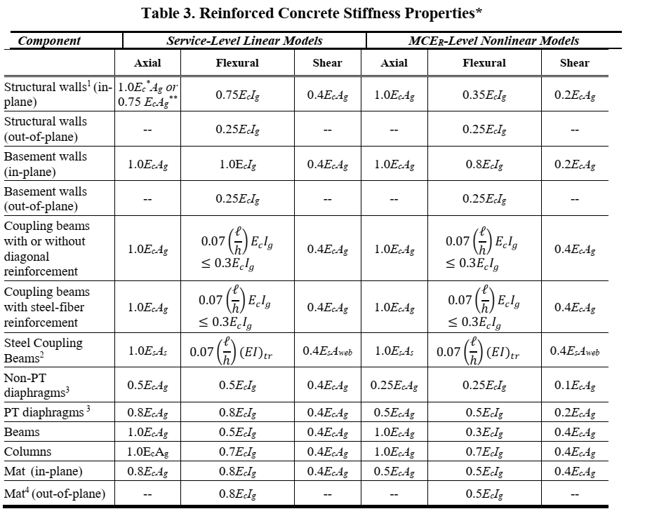
Hi; You can use the values listed for MCE(R) for your linear static/dynamic analysis based on a DBE earthquake. -

"The PMM interaction surface is not convex" - SAP2000
Badar (BAZ) replied to Suarez's topic in Seismic Design
This is most likely not a serious error; it will not have drastic effect on the behavior of the member. You might want to take a look at the hinge properties. -
I am not in a position to comment on the part related to properties of concrete. There can be number of reasons for it. Shrinkage is most obvious one. Do they have reasonable spacing of temp and shrinkage rebars, if any? Are cracks wide enough to lead to yielding in rebars? Have you established the structural adequacy to eliminate the possibility of structural cracks?
-
The concept: Member deforms when it receives nodal forces which can be axial, moment, torsion, and shear acting either individually or in combination with other types. In its deformed shape, the gravity force tends to deform the structural member further, thus leading to an increase in end moments. These are called second order effects. These effects are significant for slender members only. In addition, code requires you to check the drifts in your structure with an analysis that incorporates this P-delta effect so as not to underestimate . If P-delta analysis does not converge: Check model for connectivity issues Check model for cantilever elements not connected to slab or any other bracing member check meshing P-delta analysis also fails to converge is you have membrane assignment to your area elements if all of above is ok, make it stiffer.
-
Can you show entire floor along with location of area where you are checking deflections. From your results of with/without slab and the partial snapshot, it appears as if it has one-way distribution. Your secondary beam might be framed in a way that is leading to an increase in deflection rather that other way around.
- 6 replies
-
- etabs
- secondary beams
-
(and 1 more)
Tagged with:
-
Have you compared the deflection with and without the secondary beam?
- 6 replies
-
- etabs
- secondary beams
-
(and 1 more)
Tagged with:
-
I think your reading of the results given by ETABS is not reasonable. Also floors is incorrect terminology to be used here, I reckon you mean two slab panels. If two slab panels are connected by a pin-end secondary beam supported on fixed-end beams, you will get more deflections in that panel as compared to the model in which secondary beam can transfer end moments to primary beams.
- 6 replies
-
- etabs
- secondary beams
-
(and 1 more)
Tagged with:
-

What foundation is most suitable for a house close to the sea?
Badar (BAZ) replied to symakhan's topic in Concrete Design
Please leave it to some one who understands it better. After reading your post, I think, you are not the right person ( from practical building construction point of view) to get the advice. -

Structural Assessment of Not-so-old Existing Buildings
Badar (BAZ) replied to SAL9000's topic in Seismic Design
The codes that deal with existing structures have detailed guidelines regarding collection of data regarding in-situ material properties and geometry of structure. Consequently, the code allows to use higher strength reduction factors if your confidence in the existing material properties is high. In addition, they provide guidelines regarding nonlinear modelling as well. Based on these, you should decide which code to follow. In my opinion, for a relatively new building, you can use ACI 318's/ASCE 7's latest guidelines to check its adequacy. If if fails that test, then ASCE 41's latest guidelines may result in better assessment of structure. -

PMM Ratio of Top Column is Higher than Bottom Column
Badar (BAZ) replied to Jibran's topic in Concrete Design
Study the PMM diagram. For column at top floor, small axial load coupled with relatively large moment is causing your PMM ratio to shoot up. -

Help needed with Disaster Resilient Masonry House Structure
Badar (BAZ) replied to Omer Ahmed's topic in General Discussion
"There is no favorable wind for sailor who does not know where to go". You are asking wrong questions. Whatever I write, will misguide you. -

Help needed with Disaster Resilient Masonry House Structure
Badar (BAZ) replied to Omer Ahmed's topic in General Discussion
Use ACI 530-11 for the reference. You do not need a software for these structures, unless you want to know the design shear on individual wall panels. For most masonry buildings (rectangular shape with no vertical irregularities, normal size rooms, and only the normal size window and door openings) you do not even need to consult any code or use software. You should be able to design these kind of structures in 30 minutes. -

Long Term Deflection Check in 2 way slab system
Badar (BAZ) replied to Junaid Waheed's topic in Concrete Design
Design your floor system by checking the "ignore vertical offsets in non P/T Models". It is performing incorrect analysis when you uncheck this option; you can compare the shape of bending moment diagram in beams as a reference. It gives a weird shape when you uncheck this option. Ignoring or considering the 2D analysis only will have negligible effect. -

Long Term Deflection Check in 2 way slab system
Badar (BAZ) replied to Junaid Waheed's topic in Concrete Design
For gravity loads, and for the purpose of deflection check ( which needs to be checked against gravity loads), it is reasonable to use 2D analysis option. Even if your are using 3D analysis by unchecking this option, your results should approximately be the same, as you are using gravity loads only. Another scenario where this option can lead to considerably different results is when you have angled columns. Vertical offsets are used to model raised and depressed slab panels. If you have not modelled them, it does not matter if that option is checked or not. How much is the difference in results in terms of percentage? I doubt if your results are differing by considerable amount. -
Yes, You can reduce. ACI 318 calls them Architectural Columns, See following sections of ACI 318-14 ACI 318-14 (R10.3.1.2) But, you need to be careful in areas where ductility demand is high.
-

Tension force @ top of retaining wall
Badar (BAZ) replied to Muhammad Hashmi's topic in Concrete Design
WS- Could the comment be about the reaction forces exerted by the wall under consideration on the wall which is at 90 degree angle? The shear at the wall-wall joint will be the tension to be resisted by the orthogonal wall. -

High reinforcement in middle story column
Badar (BAZ) replied to M.Faheem khan's topic in Concrete Design
If you have included the retaining walls in your model, and have lateral loads as well, then you should expect these results. -

Etabs - Story Max/Avg Displacements Report missing
Badar (BAZ) replied to Muhammad Hamad's topic in Seismic Design
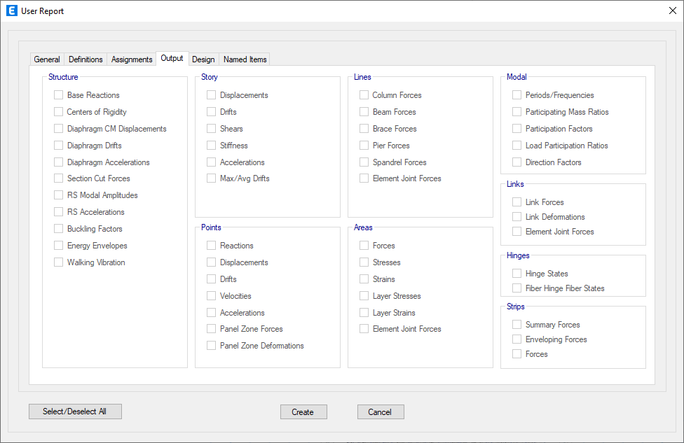
Go to reports tab, and select Max/Avg Drifts option under "Story" section of the dialog box. You can get the same result in the excel format if you go to Display options, select Show tables, and then choose the Max. Avg Drifts- 1 reply
-
- torsional irregularity
- etabs
-
(and 1 more)
Tagged with:
-
Change of stiffness would probably not effect the results in a desirable way. There are guidelines in ACI-318 regarding the stiffness modifiers; The value of modifiers depend on weather the walls are in tension or compression. You need to: add more walls if they are failing in shear at multiple levels do a envelope analysis ( upper and lower bound forces) if they are failing in shear due to back-stay effect. Check your loading to see if you have over-estimated them
- 1 reply
-
- shearwall modifiers
- shearwall etabs
- (and 4 more)
-
Design column moments after P-delta analysis are exceeding the code limit of 1.4 times the moments due to 1st degree analysis. Check any member by manual calculations to make sure that the change in member ( column, beams, or both) size is required. In addition, you can do following: ETABS uses a default value of 1 for effective length factors; you should revise the factor if you have stiffer beams. you can also review moment coefficient factor. make sure that unbraced length ratios are correct.
-
Box girders would span between columns. What do you have in mind for the region of middle strips? I think you might end up spending more on man hours, shuttering and probably reinforcement. If you do want to make foundation light, go for post-tensioned floor systems. Structural engineers, in Pakistan, are very reluctant to adopt this widely accepted system, around the world, in buildings. If they can afford to spend more on labor, engage it on this. It will help developer, as you will be able to add additional floors for the same total height of building.
-
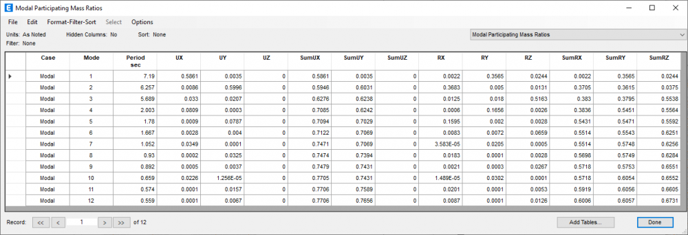
Waslaam, Your first two modes are not torsion. Torsional mass participation (Rz) is negligible in first two modes. Your first two modes are predominately translational in nature. See the attached table for reference.


