
Badar (BAZ)
-
Posts
518 -
Joined
-
Last visited
-
Days Won
279
Content Type
Profiles
Forums
Events
Everything posted by Badar (BAZ)
-
Hinges at both levels only can lead to the loss of gravity-load-carrying capacity.
-
Yes, you can transfer forces generated by corbel (axial, moment and shear) to the column for analysis of column in ETABS.
-
Yes, it should be structurally-viable framing option.
-
For 1: It depends on the size of your riser relative to tread. 2: Yes.
-
Yes, it can be ignored at the top story if it is only at the top beam-column joint. The ratio should be satisfied at the bottom of the top story.
-
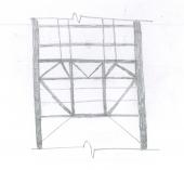
You should have modeled it as a simply supported member. For lateral stiffness, bracing members in the vertical plane could have been used. For simply supported case, you can assign truss member to bottom and top chord as well. If the girder is stiff, and you have chosen the loads correctly, the girder will cater for serviceability and design concerns.
-

two way beams and slab design using CSI SAFE
Badar (BAZ) replied to Muhanad's topic in Concrete Design
Looking at the beam layout in Figure titled Cantilever-1, I can judge that you have one-way slab panels. Check the ratio of long to the short side of your slab panels. So, you don't need to take strip moments from ETABS/SAFE. Yes, end moments of your beams are not correct. Check the connectivity of nodes in your model. -
Sorry, I m not sure what you meant. You don't need to include a member in the model just to add its load. You need to model only those members that are essential for completing the load path (structural members).
-
Plate connection in compression and bending
Badar (BAZ) replied to groszni awesome's topic in Steel Design
Looking at the figure, one cannot figure out the complete load path for a particular loading scenario. So, it is not possible to give a specific advice. But, the way these pipes are connected, there be moment due to the eccentricity of connections in addition to axial forces. In addition to axial and flexural stress, shear stresses can also dictate the thickness required for the pipe, if the load path includes these forces. -
RC Beam with Set down Analysis and Detailing
Badar (BAZ) replied to Don Ruc's topic in Concrete Design
For local behavior, the beam should do just fine. -
The beam is a flexural member, and the column is an axial+flexural member. So, the beam will experience more cracking than columns. These numbers are deduced from experimental results ( read the commentary of ACI section 10.10.4.1).
-
Material behavior can be idealized as consisting of an 'elastic' domain and a 'plastic' domain. For almost 200 years, structural design has been based on an elastic theory which assumes that structures display a linear response throughout their loading history, ignoring the post-yielding stage of behavior. Current design practice for reinforced concrete structures is a curious blend of elastic analysis to compute forces and moments, plasticity theory to proportion cross-sections for the moment and axial, load, and empirical mumbo-jumbo to proportion members for shear. From the book "Design of Concrete Structures with Stress Fields" by A. Muttoni, J. Schwartz and B.Thurliman.
-
Draw the shear force diagram for one way shear. Calculate the design bearing pressure for determining the demand for resistance against punching.
-
The demand on the horizontal and vertical members that will transfer the forces of a wall to the foundation is a major concern. The demand will be calculated by considering the expected ductility and overstrength of the wall.
-
Consult the document titled BRACING FOR STABILITY. Bracing is a function of the compressive strength of compression flange. As a rule of thumb, bracing force can be considered as 2-3% of the coompressive strength of the compression flange of beam. Read the document for better estimate.
-
The time history is the most accurate way to estimate the demand as well as detect the shortcoming in a structure. It is time-consuming and most design offices do not use it unless they have specifically charged from the client for such analysis. If your building is regular, response spectrum will suffice; you can check modal mass participation to verify that. If you are getting more than 60% mass in principle modes, then time history will not offer a significant advantage.
-
You will use Time history analysis when you want the analysis done in highest possible detail. Yes, it will depend on the building height, as well as on the structural irregularities. For regular structures less than 20 stories, pushover analysis will do. But if you want to consider the effect of higher in modes even in buildings less than 20 stories, you should go for Time history analysis.
-
Study section 11.2.1.2 of ACI 318-11. The relation you have mentioned above does not include the effect of axial forces.
-
Boundary Element length determining query.
Badar (BAZ) replied to Muqtadir's topic in Concrete Design
ETABS reports the depth of neutral axis, as well as the required length of boundary element. -
Yes, Errect formwork, place and hold reinforcement and pour concrete in shifts.
-
Boundary Element length determining query.
Badar (BAZ) replied to Muqtadir's topic in Concrete Design
You can also get help from: Reinforced concrete design, 6th Ed., by Mac Gregor and James K Wright and Seismic Design of Reinforced Concrete and Masonry buildings by Paulay & Priestely. -
Isolated footing that ensures yielding of column at base
Badar (BAZ) replied to Badar (BAZ)'s topic in Foundation Design
The analysis is not limited to high seismic zones and it is also not limited to weaker soils. That is why I posted it. We assume that hinge will form if longitudinal reinforcement of vertical members can develop 1.25fy, but that is not the only criteria. The author says that capacity design approach should be used for proportioning foundation. The proportioning of foundation for the design seismic forces is not enough. -
Isolated footing that ensures yielding of column at base
Badar (BAZ) replied to Badar (BAZ)'s topic in Foundation Design
I posted the query because I recently read two articles: one is FOUNDATIONS FOR SHEAR WALL STRUCTURES by J.R. Binney and T Paulay, and the other one FOUNDATIONS FOR CAPACITY DESIGNED S T R U C T U R E S by P.W. Taylor and R.L. Williams. @Rana : This is not enough. These details ensure the development of column hinge at the bottom if it is possible. And that "if" depends on the soil-structure interaction and the strength of the soil. If the soil is strong enough to resist bearing pressure corresponding to forces (axial load + moment) that it may experience when the column will be in inelastic range (capacity design approach), and if you have designed the footing for the moment that it may experience when hinge (capacity design approach) will form in the column, which is, of course, greater than the moment that you will get from ETABS for the design Earthquake, then the hinge will form in the column. If the above scenario is not feasible then you may proportion the footing to allow the rocking behavior so that energy may be dissipated provided footing rotation is in permissible limits, which will depend on the soil-rotation relationship. @umer: In MAT, or other connected foundation types, the third option is to allow nonlinear behavior in the foundation. In that case, the foundation should be detailed for attaining necessary ductility levels. These things are not discussed in the ACI code. I have not read these things in RCC books as well. -
Does anyone practice the design philosophy that ensures the formation of plastic hinges at the bottom of the column, near the foundation, for isolated footing?
-
Yes, 2D plate analysis should be used. 3D analysis will give wrong results as the raft has confinement on all sides. If you are using the 3D analysis, then you must add lateral springs as well to get better results.

