-
Posts
518 -
Joined
-
Last visited
-
Days Won
280
Content Type
Profiles
Forums
Events
Everything posted by Badar (BAZ)
-
I hold the same opinion on this topic.
-
I meant that.
- 29 replies
-
- t-computed less than ta
- base shear time period
- (and 3 more)
-

SEISMIC FORCES ON FRAME SUPPORTED WATER TANK
Badar (BAZ) replied to Badar (BAZ)'s topic in Journal/ Articles/ Tutorials
Is there a slab at mid level?- 6 replies
-
- water tank
- overhead water tank
- (and 2 more)
-
The post contains an attachment containing the seismic analysis of the over head water tank, performed by using guidelines of ACI 350.3-06. The report doesn't address every structural component, but can serve as reference for anyone who wants to check the frame-supported overhead water tank for seismic forces. Water tank Seismic FORCES - SEFP.pdf
- 6 replies
-
- water tank
- overhead water tank
- (and 2 more)
-

Deflection Calculations : Manual vs Etabs
Badar (BAZ) replied to Waqas Haider's topic in Concrete Design
The modifier -0.35- is not meant to be used for calculating deflections of flexural members for gravity loads; It is to be used for calculating lateral deflections of the frame. You can make multiple models on Etabs to perform the calculation. It is better to use excel sheet. I do not perform these calculations on ETABS. Safe is another option to perform these calculations.- 2 replies
-
- deflection check
- minimum thickness
-
(and 2 more)
Tagged with:
-

Incorrect floor framing
Badar (BAZ) replied to Badar (BAZ)'s topic in Engineering Marvels & Disasters
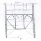
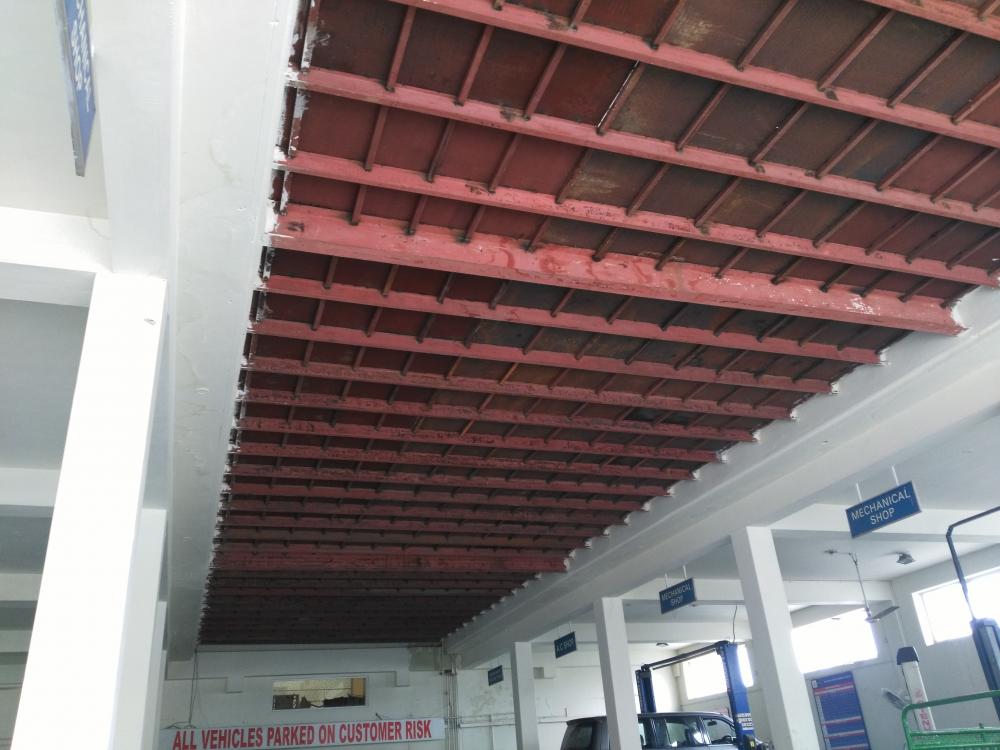
The beam with larger depth should be the main beam, and the beam smaller depth should be the secondary beam. By main beam, I mean that the beam has ability to attract forces from adjoining members because of its larger stiffness. Keeping that thing in mind, secondary beams should have been transferring the reaction directly to main beams, and main beams should have been transferring the loads of secondary beams, which are carrying the load of metal deck and the live load, to concrete beams. In the figure, they have placed larger and smaller size beams in the same directions. If smaller size are able to carry load, as is evident from the standing structure, why use larger beams. They have wasted material. -
The term might have been used by some author; it is not a common term. Where did you read it?
-
Some portion of slab is used by many engineers to take into the account the effect of line load on the slab. Many call it a beam, because the reinforcement arrangement resembles like a beam. But it cannot technically be called a beam; beam is a member that attracts force by virtue of its stiffness. Since, the thickness of so called beam is equal to that a slab, it cannot attract forces. It is a simplified way of taking into the account the effect of line load on slab; by arranging reinforcement in this way, one assumes that the effect of line load will be limited within the width of so called beam. So the width of the beam will be decided by the design moment. The beam will be only designed for the load of the supported wall, or the load of supported wall + the load transferred by the wall from upper levels. The so called beam cannot take any load from adjacent slab area, as it does not have the stiffness to attract any load. So tributary area thing is not applicable to that member. If you understand what is written above, you should conclude that there is no need to check the deflection. In many cases, this way of locally reinforcing the slab ( so called concealed beam) will not be able to support the load transferred from above levels, unless you increase the thickness of slab.
-
I meant that you should understand the section 10.10 of ACI 318-11, or earlier versions, so that you can check if members of the frame will have second lorder effects or not. P-delta effects not need to be considered in certain situations only.
-
Dear Abid Qasmi, Read the section 10.10 of ACI 318-11. One should check slenderness limits given in the section 10.10.1 to decide if second order effects will be significant or not. The limits given in the section 10.10.1 depends upon the type of frame (sway or non-sway). ACI gives us three ways of deciding whether the frame is sway or non-sway. One is to check stability index, second is compare stiffness of columns and bracing elements and third is to compare first order and final moments( including second order moments).
-
That is how ETABS decides the location of base of base shear. The height of the building above the bottom story level is used by Etabs to calculate time period.
-
Define a story level where you want to impart your base shear. Then in the input table of seismic loads, set bottom story as that story.
-
-
You have added to my pool of knowledge. I had not gone through the 2014 edition of the ACI 318 code yet. The picture that you attached should concern with loadings in which pre-yield behavior is taken into the account to calculate deformations. My earlier comments were related to deformations related to design level seismic forces. Read the following excerpt form the commentary of the section 6.6.3.1.2 of 318-14. The type of lateral load analysis affects the selection of appropriate effective stiffness values. For analyses with wind loading, where it is desirable to prevent nonlinear action in the structure, effective stiffnesses representative of pre-yield behavior may be appropriate. For earthquake-induced loading, the level of nonlinear deformation depends on the intended structural performance and earthquake recurrence interval. As UBC 97, or any other building code, wants us to compare design level drift to maximum inelastic drift, one should use stiffness modifiers that reflect the yielding of the member. If one is using performance based approach, these modifiers can change. (I am talking about seismic forces)
- 16 replies
-
- stiffness modifier
- cracked section
-
(and 2 more)
Tagged with:
-
You have got it wrong. One needs to satisfy drift limits by considering the loss of stiffness due to cracking. The code has specifically directed us to do that. I will give you the reference of UBC 97. For the determination of design level displacement, the code says, "The mathematical model shall comply with Section 1630.1.2." The section says : Stiffness properties of reinforced concrete and masonry elements shall consider the effects of cracked sections". Can't comment anymore on that.
- 16 replies
-
- stiffness modifier
- cracked section
-
(and 2 more)
Tagged with:
-
As I have already written above, we don't need to apply stiffness modifiers in order to get design forces. Crack is a general term. In RCC structures, we avoid shear and anchorage failure and intend that structure fail in flexure if loads exceed the design limit. As far as seismic design is concerned, we follow capacity design approach. In this approach we avoid brittle modes of failure (such as shear and anchorage) and make sure that element is designed for shear, or anchorage forces, that will result from inelastic deformations in ductile range. We also want that the flexural failure of beams occur before the flexural failure of column (if the structural system has moment resisting frame) in case of major seismic event. We also want that the diaphragm and foundation behaves elastically.
- 16 replies
-
- stiffness modifier
- cracked section
-
(and 2 more)
Tagged with:
-
Use the principle of superposition to calculate the combined effect of moment and axial force (P/A +- My/I).
- 16 replies
-
- stiffness modifier
- cracked section
-
(and 2 more)
Tagged with:
-
This is from the commentary of code: " If the factored moments and shears from an analysis based on the moment of inertia of a wall, taken equal to 0.70Ig, indicate that the wall will crack in flexure, based on the modulus of rupture, the analysis should be repeated with I =0.35Ig in those stories where cracking is predicted using factored loads."
- 16 replies
-
- stiffness modifier
- cracked section
-
(and 2 more)
Tagged with:
-
Use these stiffness modifiers to satisfy the drift requirement of the code. You shouldn't use the values lesser than the ones provided by the code; they are already on the conservative side. Do not use these modifiers to check the strength demand of individual members. Make another model, without applying any modifier, to check the strength-demand. These stiffness modifiers will result in a design in which you would under-estimate the demand in beams, and over-estimate in columns. The value of stiffness modifier for the wall depends on weather the wall is in tension, or not. If the edge of the wall is in tension, then the modifier is 0.35.
- 16 replies
-
- stiffness modifier
- cracked section
-
(and 2 more)
Tagged with:
-
As it is a reinforced concrete structure, the sliding should not be a concern due to the self-weight of the structure; same goes for overturning moment. The consideration of the frost penetration will govern the depth, if applicable. IF there is SOG, it can also govern the minimum possible depth of the footing. Why would you ask that? How can a retaining wall transfer any thrust to the foundation? There is no need to split the structure of this size in three portions. What is dynamic stiffness? I have not come across this term before in relation to the structural design of a building.
-
According to the section 10.10.6.5 and its commentary (of ACI 318-08), we do not need to use minimum eccentricity if there are negligible second order effects.
- 29 replies
-
- t-computed less than ta
- base shear time period
- (and 3 more)
-
P-delta analysis is the study of the increase in lateral deformations of structure due to gravity loads acting on the deformed shape of structure. So, we need to include the effect of stiffness-reduction of reinforced concrete members, due to cracking, to get the better estimate of P-delta effect. Yes, it is the issue. You need to be careful about the results of column from ETABS. Read this post as well: http://www.sepakistan.com/topic/2008-issues-in-etabs-results/#comment-5713
-
In that case, special seismic load combos are applicable to the beam that is transferring column forces of 8 stories to the shear wall.
-
You can choose both codes to proportion your shear walls for design loads. I suggest, go with the latest version of ACI 318. If I understand correctly, your shear wall is supporting columns. In this case, special seismic affects do not apply. They would have valid for columns, if your columns were supporting the shear wall.


