Badar (BAZ)
-
Posts
518 -
Joined
-
Last visited
-
Days Won
279
Content Type
Profiles
Forums
Events
Everything posted by Badar (BAZ)
-
Yes. Why it would'nt be?
-

Contraction Related Damage Of Rcc
Badar (BAZ) replied to Badar (BAZ)'s topic in Engineering Marvels & Disasters
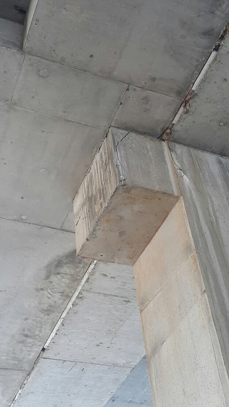
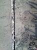
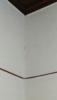
Building paper was provided at one level. The performance was better at that level, but there was spalling at that level as well. -
Concrete cracks when it is restrained to conract, or expand. We all kow that. But, I never imgained that the failure to give due regard to cater for this property of concrete at deisgn phase can lead to grave consequences. A structure was provided expansion/seismic joint at a distance of about 200ft. It is normal practice to do that. But normally, two columns are provided at the joint to suport end-spans. But, in this case, the end panel was supported on corbel which was attached to the column loacated next to exapnsion/contraction joint. Floors of the building contracted, approximately, 4 months after the pour. This resulted in the damage of corbel, or the beams supported on corbel. Damage to two corbels was limited to the spalling of concrete, as depicted in attached pictures. In two joints, end of beams also cracked along with the corbel. A part from contraction of concrete, observation also shows the importance of frictional forces. There is a huge opening at one of floor. Could this lead to un-equal contraction of floors, leading to an increase in stresses? What could have been done to improve the performance? Any ideas.


- 3 replies
-
- 1
-

-
- temperature change
- cracks
- (and 1 more)
-
Slenderness Ratio Check For Columns By Etabs
Badar (BAZ) replied to Muhammad Sohail Khan's topic in Concrete Design
You can override the dafult settings; remove the option in Etabs that is used to consider minimum eccentricity in short column. -
Axial Load In Beams From Temperature Too High
Badar (BAZ) replied to mhdhamood's topic in Concrete Design
Assuming you got right values of axial forces, the beam theory is not applicable in this case. You need to design your member for combined effect of axial and bending stresses. You have not mentioned the nature of axial forces; they should be tensile forces. -
I would also design it as a continuous member. The ability of this member to tranfer moments across drop will depend upon detailing, and the sample detailing in the picture does not seem adequate; there should be a double bend (u-shaped hook ) instead of the standarad L shaped.
-
Is there any way to model boundary-element of shear wall in ETABS. Has anybody checked the validiality of using the line element as boundary-element at ends of shell element.
-
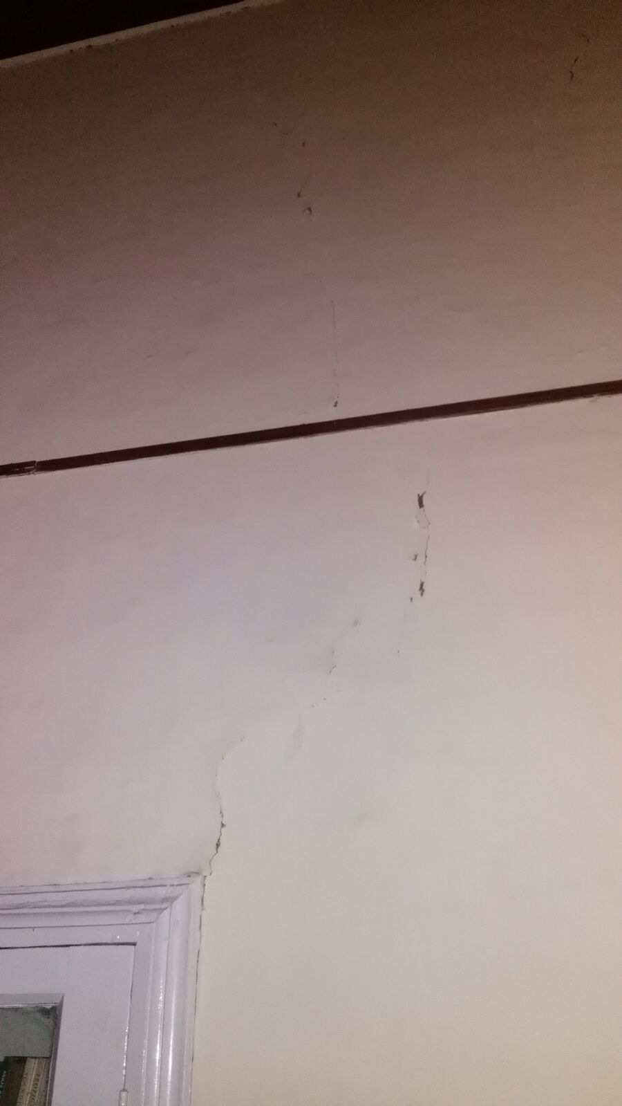
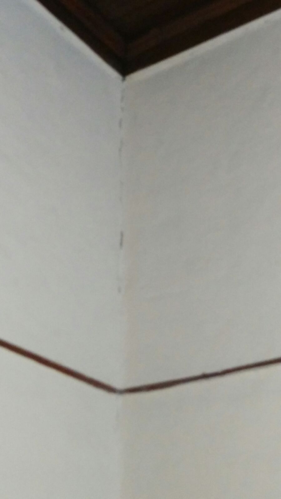
Damage In Stone-Masonry After Seismic Event
Badar (BAZ) replied to Badar (BAZ)'s topic in Seismic Design
I don't have roof pictures. CGI sheet and purlins act as diaphram. -
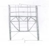
I recently visited a residential building, located in Kehal area of Abbottabad. The visit was made to visually-inspect the building in order to ascertain if the building sustained any structural damage due to the 7.5 magnitude earthquake that jolted many parts of the country on 26th October 2015. The structure is a single story stone-masonry building with mud plaster on walls. The roof of the building consists of wooden rafters, purlins and C.G.I sheets. I am attaching photos to show you the damage sustained by the buiding due to the seismic event of 26th october.


-
Verification For Concealed Beam Design
Badar (BAZ) replied to Waqas Haider's topic in Concrete Design
You designed a 9 inches deep beam for 18 feet span. Nine inches does not satisfy deflection criteria of the code (ACI-318). The thickness of your slab is based oin 18ft x 14 ft dimensions of slab, which is not enough as far as deflection-control is concerned; the beam will deflect more than the desired limit which will result in un-desired deflection of slab. -
Smeared crack models are models for explaining tensile resistance of cracked concrete, or masonry. Fixed and rotating refers to the ability of crack to propagate along a fixed axis, or at an angle to the axis of previous crack. If you know the direction of propagation of crack you can use fixed crack model; if you dont, then rotating crack model should be used.
-
Looks for these documents on the web for the literature of the subject topic. computational strategies of masonry structures by Lourenco. computational modelling of concrete fracture by Rots. Elasto-plastic multifixed smeared crack model for concrete. Building response to ground movements by Holger Netzel.
-
These members act as tension, or compression members; they act like a brace. I think, they shouldn't be assigned as diaphragm.
-
The effect of torsion in beams, for reinforced concrete structures, can be neglected in most cases. Study the concepts of equilibrium and compatibility torsion.
-
I agree with Muneeb Badar's post.
-
Punching Shear Of Shear Walls In Case Of Eq "important Issue"
Badar (BAZ) replied to mhdhamood's topic in Concrete Design
I am not sure what your query is. I infer that you are talking about dealing with shear strength of floor slab around the shear wall. My question is: are you using flat plate as floor, or beam-slab system? If you are using flat plate, then you need to be worried about the shear failure of slab.- 22 replies
-
- 1
-
-
- punching shear seismic
- shearwall punching
- (and 1 more)
-
One thing that I learned while dealing with above mentioned building is that area of the floor has significant effect on structural system to resist seismic loads. The building, under discussion, has an area of about 45000 sqft/floor. The building is 4 stories, the bay length is 26ft, the column size is 30 inches, and beams are 15x30 inches. Even then, one requires shear walls of about 130 ft length in both direction to satisfy strength and serviceability requirement of code. The shear in one wall exceeds the maximum limit set by the code if one uses lesser shear walls. The problem is base story shear, which is about 5000 kipps at second level.
-
You got the appropriate advise.
-
From the figure that you have provided, you can check if torsional irregularity exist at certain level. The torsional irregularity exists when the maximum story drift at a corner including accidental torsion, is more than 1.2 times the average of the drifts at the corresponding corners. Accidental torsion is related to the minimum eccentricity between center of mass and center rigidity that must be considered at each level.
-
Seismic Drift Procedure For Real Building
Badar (BAZ) replied to mhdhamood's topic in Seismic Design
Strength design load combinations should be used to calculate the drift. Analysis should take into the account the reduction of stiffness of structural members, as well as, the effect the effect of gravity load acting on deformed shape ( second order analysis). You can check the drift only against against E. The difference is negligible for most of the structural configurations. -
You are right about it.
-
Shear Wall Beam Overstressed In Shear
Badar (BAZ) replied to Waqar Saleem's topic in Concrete Design
If the aspect ratio (span/depth) of your coupling beam is greater than 4, then model it as line element in ETABS. If aspect ratio is less than 4, then model it as area element in ETABS. Diagonal shear reinforcement is most effective if the aspect ratio is less than 2. However, code does permit its use for aspect ratios between the 2 and 4, as well. If you do not require special structural wall, you can override shear strength reduction factor: you can change it from 0.6 to 0.75. If the coupling beam still fails, tweak the structural system to lower the demand on that shear wall.- 10 replies
-
- 2
-
-
- shear wall opening
- shear wall
- (and 1 more)
-
Seismic Hoops In Zone 4 Diameter Restriction
Badar (BAZ) replied to Waqas Haider's topic in Seismic Design
Read the section 21.6.4.4 of ACI 318-08. -
Do not provide the reinforcement that can resist the moment at slab/wall joint. In other words, provide no reinforcement on the earth side, in the basement wall, at the that joint.
- 5 replies
-
- 2
-
-
- simply supported shell
- slab edge release
- (and 2 more)
-
Span of the diaphragm is the distance between vertical lateral load resisting elements. Yes, the same diaphragm can behave different in different directions. Also read and understand following statement from the article: The statement implies that when your are using shear walls in the building, the span of the diaphragm could be the distance (perpendicular to the lateral force) between shear walls, depending upon the relative stiffness of moment resisting frames and shear walls. If the building has no shear walls, then the span is the distance (perpendicular to the lateral force) between column lines, or two consecutive frames.
- 4 replies
-
- 3
-
-
- diaphragm
- diaphragm flexibility
- (and 2 more)