Badar (BAZ)
-
Posts
518 -
Joined
-
Last visited
-
Days Won
280
Content Type
Profiles
Forums
Events
Everything posted by Badar (BAZ)
-
It will require two plastic hinges to develop mechanism, as it act as propped beam, and it can still redistribute moment. You are not relying on plastic strength of the structure to carry gravity loads. If , in a particular frame, your reliability/redundancy factor is less than 1, excluding the bay which contains propped beam, and your drifts are under control, then you can use a propped beam in one bay of that frame. If you can afford a non-moment resisting bay, which means your drifts are under control and your structure has adequate redundancy, then you don't have to worry about integrity of that one joint. Other joints and bays of the frame can take care of that.
- 11 replies
-
- 2
-

-
- development length
- standard hooks
- (and 1 more)
-
You can use headed reinforcement , see section 12.6. If you cannot use headed reinforcement, and cannot provide the length of embedment for the development of top bars in tension, then consider this joint as PIN, and re-run the analysis to get the correct distribution of moments in mid span and other continuous support.
- 11 replies
-
- 1
-
-
- development length
- standard hooks
- (and 1 more)
-
You need to know the loaded area, and decide accordingly about taking the affect of that particular load as point, or UDL. If you are not sure, make two models with different types of loadings.
-
See the section 10.14 of ACI 318-08, and the section 3.1.7 of ACI 530-05.
-
It will depend on your architectural constraints and seismic zone. All these systems have different ductility ratios. You need to choose accordingly. A lateral load system may not have any columns and beams, and in that system all lateral, as well as gravity forces, are resisted by shear walls. Such system is without vertical load carrying space frame.
-
A case study worth reading for structural engineers. Please find the attached document. LeMessurier-Stands-Tall_A-Case-Study-in-Professional-Ethics.pdf
-

Deduction Of Overburden From Bearing Capacity
Badar (BAZ) replied to EngrUzair's topic in Foundation Design
I am aware of both practices. There is another practice of adding overburden in the reported value of bearing capacity (source: wl*l/8). I am also looking for the answer. As per my cursory knowledge, it depends on method of the computation of bearing capacity's value. Need to ask some competent Geo-technical engineer about it. P.S: Ignore "source: wl*l/8" -
I have never considered them; never bothered about them. You do need to know the load path. Elevator loading is considered as impact, and are usually increased by 100%. I have attached a pdf, that might be helpful to you. elevators for tall buildings.pdf
-
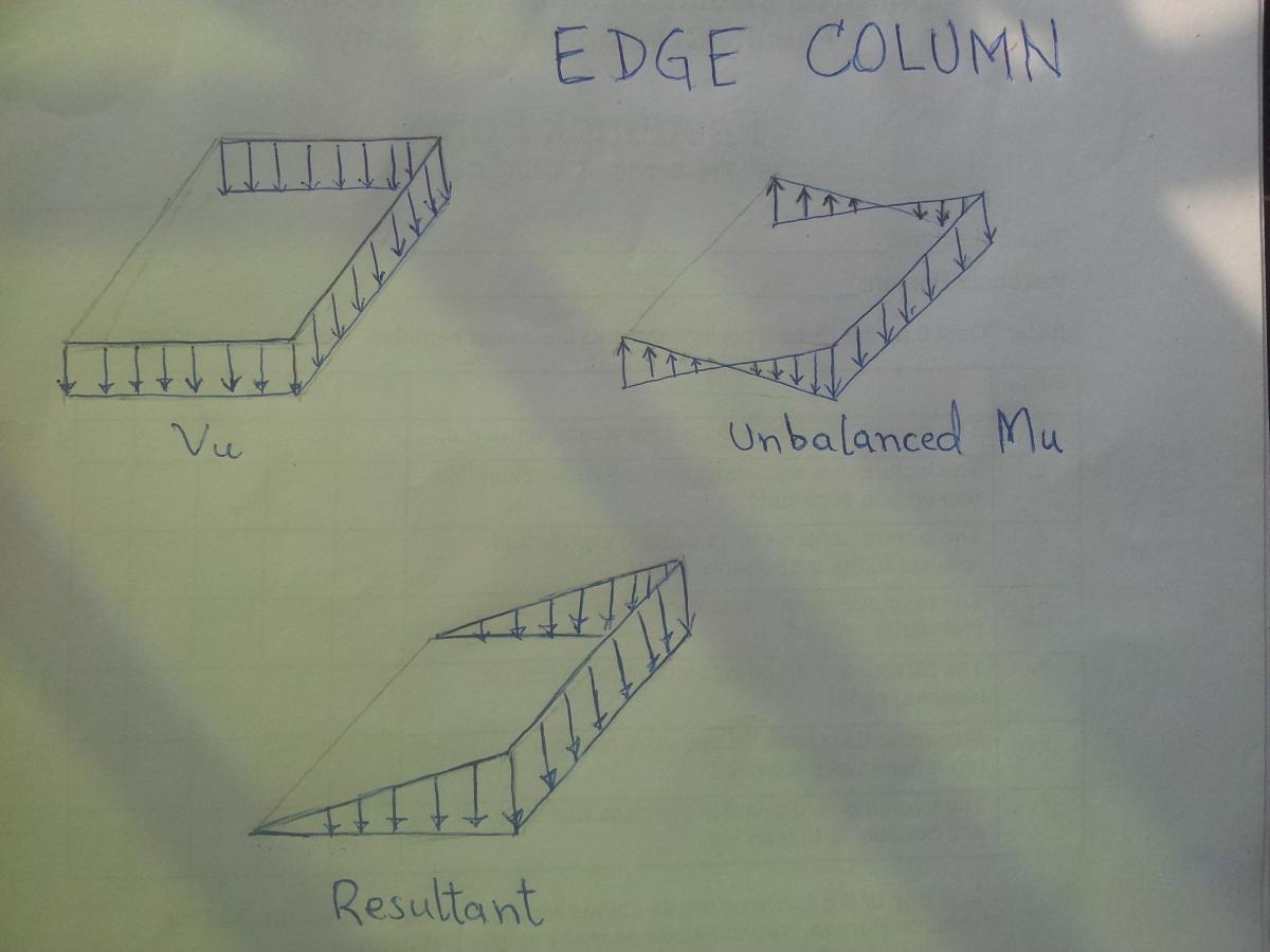
Shear Stress Distribation Due To The Transferred Moment
Badar (BAZ) replied to dr.tatish's topic in General Discussion
Shear stress on discontinued edge will be zero. I have attached a diagram, depicting distribution of shear stresses for edge column.
-
It means you need to increase, or decrease, reinforcement in beam, or column. But, You have to have a reinforcement which satisfies your elastic elastic analysis. You can't reduce the reinforcement, below the level required for resisting factored combos, to satisfy this provision. You need to add more, or reduce. But reduced moment capacity of that member should satisfy the forces of design combos. If you have provided more reinforcement than the requirement of elastic analysis, you will need to check the shear corresponding to probable moment strengths. Increase in moment capacity of member will lead to an increase in seismic-shear. I hope, I have answered your query.
- 20 replies
-
- 5
-
-
- b/c ratio
- beam/column capacity
- (and 1 more)
-
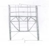
The deformed shape, on the left, is the one that will be required to maintain compatibility with deformations of VLRM. Wall can be proportioned for second order effects as a result of this deformed shape. But, these second order effects has to be negligible because there are much-much stiffer frames running in the direction of lateral forces, which will carry almost all of the forces due to second order effects, and you haven't included them in your model.The figure on the left is possible when second order effects are more than the effects that will arise due to retaining of soil, and in that case you are right. But if the effects of active earth-pressure are more, than the wall should be treated as continuous beam, and its behavior would be similar to the deformed shape shown on right. I would proportion the wall by assuming that the slab is able to provide adequate reaction. Another point is that the critical scenario for out of plane forces for wall is passive soil resistance. One has to proportion the wall by considering it as a continuous beam, supported by diaphragms. Having said that, accurate modeling, in this case, should involve spring-supports, not the hinge-support.
- 19 replies
-
- 1
-
-
- highrise with basements
- basement wall
- (and 3 more)
-
It is good to see detailed discussion on a topic, and a very good way a modelling passive resistance of soil has been presented. However, I have reservations on some comments. In this case the support condition hinge (i.e zero horizontal displacement) cannot be assumed for basement walls at slab levels as diaphragms are undergoing considerable lateral displacement.Therefore, in order to evaluate flexure in basement walls it is advised to model a line element along the height of wall (meshed at wall area edges) to compute flexure in basement walls rather than using theoretical model of prop canti-lever assumption that seems to be invalid due to diaphragm's horizontal movement . Assuming the diaphragm as rigid, there will be negligible in plane displacement of diaphragm with respect to its supports,which are vertical elements of lateral load resisting system, at particular story-level. Lateral displacement of diaphragms is with respect to story-levels. Hence, the support provided by slab to basement wall, at a particular story-level, can be considered as hinge as it will resist translational movement due to in-plane stiffness of rigid diaphragm. Why would someone be worried about out of plane displacement of basement wall, when it will be proportioned for out of plane forces( earth pressure). As it has been correctly been pointed out that drift limits in building codes are intended to control NON/STRUCTURAL damage, and to limit secondary forces due to P-delta effect. The point is: one should be worried about drift of frame (in/plane relative displacement), rather than the out of plane displacement of basement wall.
- 19 replies
-
- 3
-
-
- highrise with basements
- basement wall
- (and 3 more)
-
That usually does not happen. How many basements you have? Are your keeping the torsion in your basements in check ? Are you modeling your alone basement wall. What type of support conditions are you using? Is it RCC structure?
-
Makhzomi! you are not keeping the load path in mind. Here is how it works (as a reminder): Slab , which is acting as diaphragm for seismic loads, distributes inertial forces to vertical members, these forces are usually taken as point loads on beam-column joint, and then they are transferred to foundation through vertical element of force-resisting system. I am relating both horizontal forces (inertial and earth pressure) because both have similar load paths, except for diaphragm. Foundation of vertical elements will support horizontal loads due to both effects, slab cannot provide resistant in translational direction. It can only resist rotation of basement wall, which is what you are referring to. The reaction due to basement wall on slab will be transferred as point load to beam column joint, which will cause a drift in the frame (which is usually neglected in usual design calculations.) Joint of the frame is not restricted by the slab to drift. Slab cannot restrict it. Where will it support the reactions? Slab can only resist translational movement in its plane, but relative to its supports, which is beam column joint. And beam column joint is free to drift.
-
Lateral earth pressure will lead to out of plane deflection of wall, which will be acting as plate to this particular loading. So, they can't be combined any way. Lateral earth pressure can also also be considered as point load on beam column joint, if you want to consider its affect in the direction of seismic forces. In that case, you can add elastic drift due to earthpressure (acting as point load at one end of frame) to the inelastic drift at that level to seismic forces. But if you have satisfied drift requirements in upper stories, then there can't be a drift-related problem at basement level. There should no problem relating to drift at basement level (even if there is only one wall) even if you have not satisfied the requirement at upper levels. There are no separate reuirements for basement level, same drift limits apply. You should be looking to control torsion at the basement level as you have mentioned that the distribution of wall is unsymmetrical due to presence of seismic-joints.
-
When you will use wall, you will have different issues to deal with; beam column capacity will no more be a issue.
- 20 replies
-
- 1
-
-
- b/c ratio
- beam/column capacity
- (and 1 more)
-
It does according to the article 21.12.2.2 of ACI 318-11.
-
I want to make a comment on this very useful article. You have written: By this statement, if some one wants to reduce the moment by 25%, then the percentage to which one intends his moment to be reduced to is 75%, and the reduction factor will be more than 1. You should have written: for example is you want to reduce your moment to 25% of the original value, then the reduction factor will be .........
-
As Rana has made a comment, refer to PCA notes; they have dealt with it in detail. Yes, T-beam's deflection can be different than rectangular beam, and that depends upon location of compression force (positive or negative moment). Strength does effect deflection as stiffness is relate to compressive strength (E is related to f'c).
- 4 replies
-
- 1
-
-
- i beam
- deflection
- (and 2 more)
-
*SEFP Consistent Design* *Diaphragm Flexibility* *Doc No: 10-00-CD-0004* *Date: August 07, 2014* I am writing this article about a very important, but mostly neglected topic of flexibility of diaphragm. I used to assume that all reinforced concrete slabs can be treated as rigid diaphragms. But as it turns out, only the slab with span-to-depth (depth is length of slab in direction of lateral loads) ratio of less than 3 and without horizontal irregularity can be treated as rigid diaphragm. The more important thing is that the span-to-depth ratio and horizontal irregularity is not the only criteria and one other factor also needs to be kept in mind before assigning rigid diaphragm to concrete slabs in numerical model of building. Another important concept that I learned, and it was a moment of epiphany for me, is about TRANSFER diaphragms. I had posted a topic “Amplification Of Forces In Etabs” earlier in this forum but we were not able to reach at a satisfactory conclusion. Now, I have the answer to that query: Back Stay effect. Another article is required to explain it , and this concept is not discussed in this article. This article is about flexibility of diaphragm. Diaphragms are horizontal members of the lateral-force resisting system of building structures. Their function is to distribute inertial forces, generated at its own level, as well as other levels, to vertical members of lateral-force resisting system. One kind of diaphragm only distributes inertial forces generated at its own level. This kind of behaviour is observed in buildings where there is a continuity of vertical members of lateral-force resisting system: building should not have a setback or podium at lower levels, or below grade levels. The other kind of diaphragm, known as “Transfer diaphragm”, not only distributes inertial forces generated at its own level, but also re-distributes forces coming from upper levels. This type of behaviour is typical of a building having setback or podium at lower levels, or below grade levels. Transfer slabs can attract huge forces due to a behaviour dubbed as BACKSTAY EFFECT. Now, coming to the issue of flexibility of diaphragm. According to ASCE 7-10, In addition to considering aspect ratio and horizontal irregularity as a basis for assuming concrete slab as a rigid diaphragm, the relative stiffness of adjoining vertical lateral load resisting system. Buildings with shear walls at ends and flexible frames in between are the ones where the assumption of rigid diaphragm leads to underestimation of drifts and erroneous distribution of base shear in vertical as well as horizontal direction (1)(2)(3); shear forces in middle frames can be reduced to 23% if rigid diaphragm is assigned in the model (1) for buildings with this type of structural configuration. M. Moeini et al. (2008) (3) conducted a parametric study using numerical analysis and proposed formulae that predicts the error associated with assuming concrete slab as rigid diaphragm. They also concluded that for buildings, without shear walls, rigid diaphragm assumption is suitable for irregular buildings as well. But, for long and narrow buildings with shear walls at ends, the assumption of rigid diaphragm is not suitable. The objective of writing this article was to warn engineers about the tendency of blindly assigning rigid diaphragm to concrete slab in any type of building configuration. The result could be underestimation of forces as well as drifts. Nakashima, M., Huang, T., Lu, L-W. “ Effect of Diaphragm Flexibility on Seismic Response of Building Structures”, In proceedings of 8th world conference on earthquake engineering. San Luis Obispo, MSc Thesis , “ An Investigation of influence of diaphragm flexibility on building design through comparison of forced vibration testing and computational analysis”, 2010. M. Moeini, B. Rafzey, W.P. Howsen, “Investigation into the floor diaphragm flexibility in rectangular reinforced concrete buildings and error formulae”, In proceedings of 14th world conference on earthquake engineering. The article is not finalized and would be completed in coming weeks.
- 4 replies
-
- 9
-
-
- diaphragm
- diaphragm flexibility
- (and 2 more)
-
Ratio of flexural capacity of Beam/column is computed to preclude the formation of plastic hinges in columns for obvious reasons, refer to section 21.6.2 of ACI 318-11. Sum of flexural capacities of column at a joint should be 1.2 times the capacities of beam framing into the joint in particular direction. Etabs alerts user when the ratio exceeds; if it does not alert, it means either you are ok, or you have not activated corresponding seismic category (I think it calculates for category D E & F) for which this capacity needs to be computed. When capacity is exceeded, we can increase the size of column, or reduce the size of beam, or play with reinforcement of members. It has nothing to do with redistribution of moments; If both end of column will yield, during a seismic event, in a particular story, structure will most probably collapse. In a frame, that is resisting lateral loads, you cannot take away the ability of beam to develop negative moment; if you do not provide top reinforcement, it will not be called a moment resisting frame, and will not resist lateral loads..
- 20 replies
-
- 8
-
-

-
- b/c ratio
- beam/column capacity
- (and 1 more)
-
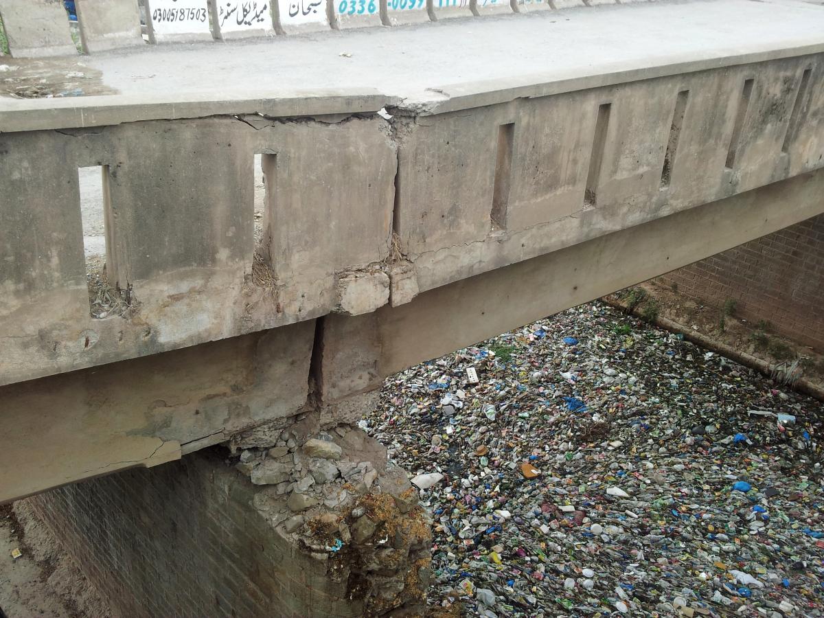
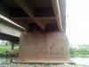
It is bridge on Lehtrar road; structural configuration of bridge consists of multiple simple spans supported on masonry piers. The bridge has failed, and it cannot be used for traffic. But, there is no sign/warning board on the road which warns people. People ride bikes on this one, and there is no mechanism to stop accidental usage of this bridge by heavily loaded vehicles, especially at night. It is a classic case of "bearing failure". Settlement might also be a contributing factor. .


-
Connection Of Truss To Supporting Beam Column
Badar (BAZ) replied to Hasan Tariq's topic in Steel Design
Pakistan building code does not provide the value of ground snow for our areas. Hence, we have to make a guess, or do statistical analysis of extreme values; both of them is based on snow data of that site. When I mentioned 40PSF, I meant ground snow load, not the design snow load. You might be right about MBMA, I don't have awareness to comment on that. -
Connection Of Truss To Supporting Beam Column
Badar (BAZ) replied to Hasan Tariq's topic in Steel Design
Hassan should have applied snow loads according to ASCE/SEI 7-05 standards, and they have given guidelines, indicating the procedure to apply even and uneven snow loads. ASE/SEI calls it as: BALANCED and UNBALANCED .- 16 replies
-
- 2
-
-
- truss connection to column
- truss connection to beam
- (and 3 more)
-
Connection Of Truss To Supporting Beam Column
Badar (BAZ) replied to Hasan Tariq's topic in Steel Design
I have few points on this comment. 1) How can you say that 40Psf is high value for snow load without asking him the location of building. The building, in question, is located in northern areas where there can be at-least 2 feet snow. 2) Your point number 1 is only valid for a situation where both top and bottom chords of truss are connected to beam. The truss in question is pratt, or Howe; consequently, only bottom chord is connected to beam.- 16 replies
-
- 2
-
-
- truss connection to column
- truss connection to beam
- (and 3 more)