-
Posts
518 -
Joined
-
Last visited
-
Days Won
280
Content Type
Profiles
Forums
Events
Everything posted by Badar (BAZ)
-
Footing design on Equivalent Static or Response Spectrum case?
Badar (BAZ) replied to Eng.Hasnain's topic in Seismic Design
There is no satisfactory answer. There is no logical answer as well. For high rise buildings, the equivalent static seismic force distribution along the height of building is incorrect. Vetting engineer wants to be on the safe side; he wants the foundation to be safe against both set of forces. -

Does torsion in the first 2 modes considered bad designed
Badar (BAZ) replied to KentNguyen's topic in Seismic Design
It is general practice to avoid torsional modes. The primary reason is that Engineers want to make their life easy; they do not want to get into the complications offered by structural system with torsion as the main response. Having said that, it is possible to design the structural system with torsion as first mode. The codes around the world penalize the engineer by forcing them to design that structure for amplified forces if torsion is under a certain limit (ratio of drifts at ends< 1.4). If the torsion is more than the limits set by code, the best way to verify such structural system is to put it through a NLTH analysis and use the Performance-Based Seismic design. -
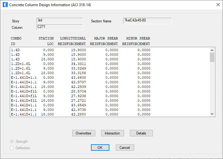
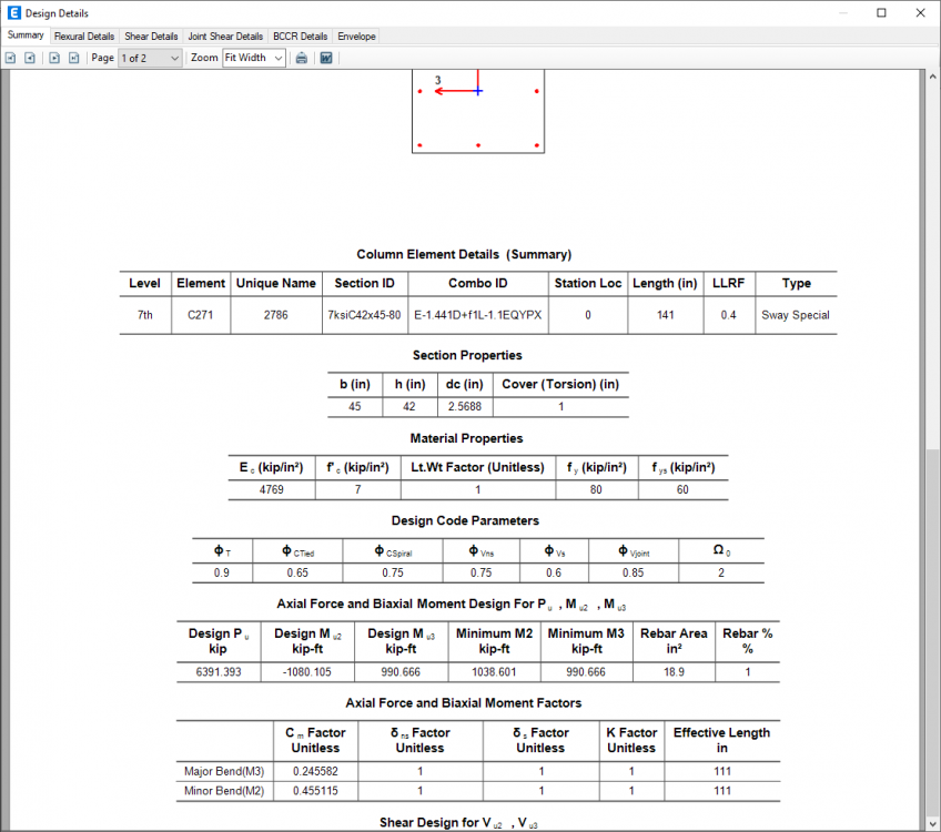
The pop-up window, displaying the table after right-click, shows the DC ratios against all the load combinations. The DC ratio visible on ETABS screen is the worst among all the load combinations. You should be able to find this in the pop-up window.
-
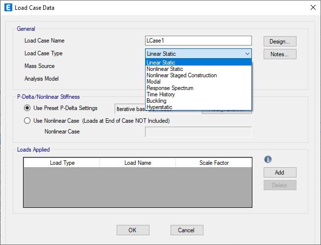
We usually model our structures in a way that lets as assign all the relevant loads on the structural model through line loads and area loads. And we usually divide gravity loads into three or more categories. For P-delta analysis, the program needs the source of gravity loads acting on the deformed state of structure. Since we already had defined those in the form of load patterns, it is convenient to use load based option. For mass based P-delta, the programme (ETABs) says: This is an approximate method which does not require an iterative solution, providing for faster computation. P-Delta is considered by treating the structure as a simplified stick model, a process which is most effective with a single rigid diaphragm at each level. Local buckling is not captured as effectively.
-
By ACI, I reckon you are referring to the ACI 318 document. That document primarily lays out guidelines for safe construction and design of some of the reinforced concrete structures. That document does not give guidelines to calculate wind, seismic, or other kind of forces. For these guidelines, you need to consult IBC, UBC, or ASCE7 documents. The inclusion of live load in seismic weight is laid out differently in US-based codes. Following are the statements from UBC 97 (Section 1630.1.1): Seismic dead load, W, is the total dead load and applicable portions of other loads listed below. 1. In storage and warehouse occupancies, a minimum of 25 percent of the floor live load shall be applicable. 2. Where a partition load is used in the floor design, a load of not less than 10 psf (0.48 kN/m2) shall be included. 3. Design snow loads of 30 psf (1.44 kN/m2) or less need not be included. Where design snow loads exceed 30 psf (1.44 kN/m2), the design snow load shall be included, but may be reduced up to 75 percent where consideration of siting, configuration and load duration warrant when approved by the building official. 4. Total weight of permanent equipment shall be included. Following are the statements from ASCE7-22 ( Section 12.7.2): 1. In areas used for storage, a minimum of 25% of the floor live load shall be included. 2. Where provision for partitions is made or where required by Section 4.3.2 in the floor load design, the actual partition weight or a minimum weight of 10 lb/ft2 (0.48 kN/m2) of floor area, whichever is greater. 3. Total operating weight of permanent equipment. 4. Where the flat roof snow load, Pf , exceeds 45 lb/ft2 (2.16 kN/m2), 15% of the uniform design snow load, regardless of actual roof slope. 5. Weight of landscaping and other materials at roof gardens and similar areas, as defined in Section 3.1.4. 6. Weight of fluids and bulk material expected to be present during normal use.
-

Load Combinations and line element RC design: SAP/Etabs
Badar (BAZ) replied to MSKhan's topic in Concrete Design
You need to look at the results again. They do show the governing load combinations. See the attached snapshots; look for combo ID. -
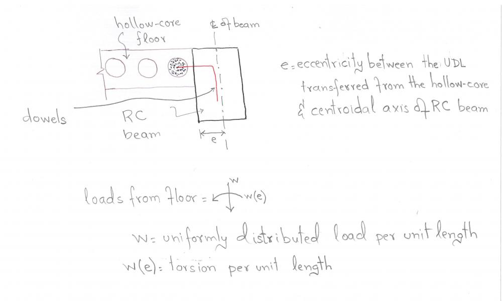
Do you understand that the supporting beam is subjected to torsion, in addition to shear and bending moment, due to connection detail chosen for transferring forces from the precast hollow-core slab to RC beam? Can you imagine what will happen if beam has not been designed for the interaction of torsion and shear? Can you imagine that the beam will tend to twist or rotate about its longitudinal axis if the adequate amount of torsional reinforcement is not present? What will be the result of that rotation? In this case, can it lead to an increase in connection forces that may not have been accounted for?
-
Rigid diaphragm is reasonable assumption for this kind of arrangement for vertical members of lateral-structural system. I already answered the issue of torsion constant. In the first run, analyze the section with out using any reduction in constant for torsion (use 1). Make changes if you are redistricted in the choice of section size for beam. In this case, how will you know if the additional flexural demands in hollow-core panels, due to torsion-related cracking in RC beam, will be taken into account?
-
Straying away from your questions, I am curious how will the construction of floor-system with these connection details take place? Will they cast the frame with rectangular X-sections of beams first, and then install the panels? Will they drill the dowels afterwards? Will the dowels be left in place during pouring of concrete for RC beams. How will they adjust the dowels at their right position in precast hollow-core panels? For these kind of construction, I have seen following construction methodologies: 1- Hollow-core panels supported on ledges of RC/Pre-case beams. 2- Hollow-core panels supported on horizontal joint of RC beams. In this case, they do not pour concrete on the full depth of beam, leaving room equal to the thickness of floor on top of horizontal joint with-in beam's depth.
-
I do not have enough information about your framing to comment on that. Generally speaking, this assignment, in most cases, has a limited effect on elements of Vertical Lateral load resisting system. When Structural Engineers intend to check forces in chord members of diaphragm, for the purpose of estimating its suitability to transfer lateral forces to vertical elements, they use this semi-rigid option. The rigid-option does not let you check these diaphragm forces. The assignment also depends on your structural system. CSi has a simple video on it. You cannot assign membrane behavior to column. You can assign membrane behavior to shear walls. It is reasonable simplification for a majority of design scenarios.
-
My name is Badar. You are addressing me with the wrong name. It seems that you are not able to realize that the eccentric nature of connection between cast-in-place beam and pre-cast hollow core slab will transfer torsion in addition to the UDL in the beam. It is better, in this case, to design the beam for the torsion due to eccentric transfer to shear between slab-beam interface. Do not use 0.35 modifier for torsional constant. The practice of using a modifier <1 for torsional constant is for monolithic construction involving combability torsion, which is due to the transfer of negative moment from slab end to the supporting beam (you do not have these moments because of your connection detail).
-
This approach will give you the same behavior as membrane. I am not sure about your intent. The UDL is not the only effect of connection that you intend to use. Let me explain it this way: The beams supporting the ends of one-way ribs of hollow-core floor system will need to be loaded with the line load and torsion. See the attachment.
-
Yes, membrane assignment will do the job assuming that you are only concerned abut estimation of demands on the frame elements and not the hollow-core slab itself. With your shear connection detail between beam and slab in the form of rebar-dowels, it would be wrong to model the slab with flexural stiffness (shell) , as it would lead to an underestimation of flexural demands on beams.
-
This structural element has shear, flexural and axial stiffness. It is not a membrane. Having said that, you can model it as membrane; You need to decide about the modelling approach based on your design assumptions for supporting members and structural system as whole.
-
Manual calculations can be done by using one of the various moment coefficients methods, which are based on elastic thin plate theory. You can consult following references which gives moment coefficients for various end conditions of plate: 1) Moments and reactions for rectangular plates-Engineering Monograph 27. Here is the link: https://www.usbr.gov/tsc/techreferences/hydraulics_lab/pubs/EM/EM27.pdf 2) Rectangular concrete tanks, 5th Edition by Javed Munshi 3) Reinforced Concrete Designers Handbook_11th Edition by Reynolds & Steedman Needless to say that you can also use software.
-
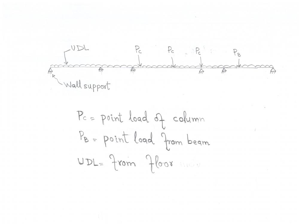
This is complicated framing. Make a line model of every beam in some software, load it properly, provide reasonable restraints, make load combinations, run 2D analysis and take out variation of moment and shear for various load combinations. You will now the location of design shear, and moment from that. Consult a book on RC to help you decide rebar requirement from moment and shear. It is pretty basic. I have attached a sketch of one of the beams which you can use as a reference to model. Correct estimation of point loads and UDL is key .
-
You can use section 8.5.4.2 of ACI 318-19 as a reference for acceptable location of openings.
-

Connection between wall and slab of ground floor
Badar (BAZ) replied to Kirill's topic in Concrete Design
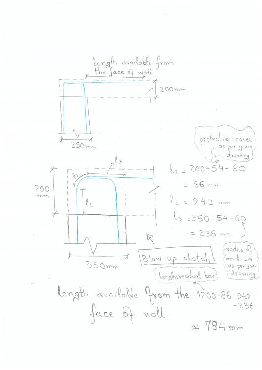
It appears that you have misunderstood the point about available length of residual bar that can serve the demand of negative moment. You do not have 990mm. I have already addressed that: You can provide extra rebars as per details shown by Ayesha. It is what it is! You cannot avoid them. What you can do is to limit their width so that the structure can have an longer service life, and the rebars remain corrosion free. I hope you understand that main/non-main depends on whether there is one-way or two-way action. -

Connection between wall and slab of ground floor
Badar (BAZ) replied to Kirill's topic in Concrete Design
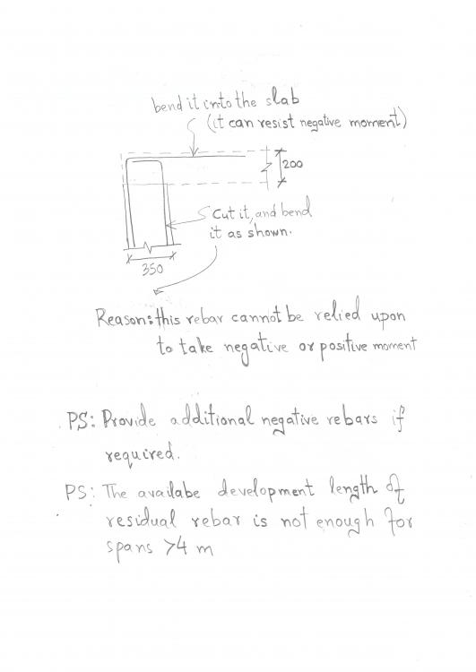
Negative rebars are the ones near the top of slab. With respect to my figure, it is the wall-rebar bent into the slab near its top face. It is a widely accepted practice to extend the top (negative) rebars to a distance of about span/4 from the face of support. For a 4m span, this would mean that you require 1m. But, as per your drawings, you do not have 1m; the available length of residual bars from the face of wall is about 1200 -150-300= 750. So you need extra rebars as per the detail shown in the comments of Ayesha for those spans. PS: In RCC structures there is no one-fits-all solutions. There are multiple loads paths. Even if you do not provide the lengths mentioned above, the slab can still have the required strength if you have provided extra reinforcement in the mid-span (i.e bottom bars). The difference will be that you might get wider cracks (on top near slab to wall connection) if you do not follow the detail suggested in my comments. But, you may not get to see them ever as flooring on the slab will make them invisible. This is the reason many engineers and contractors will say to you that do not worry about top rebars. -

Connection between wall and slab of ground floor
Badar (BAZ) replied to Kirill's topic in Concrete Design
As I understand, you want to know what to do with residual rebars of basement walls. This is what I have to say about it: -
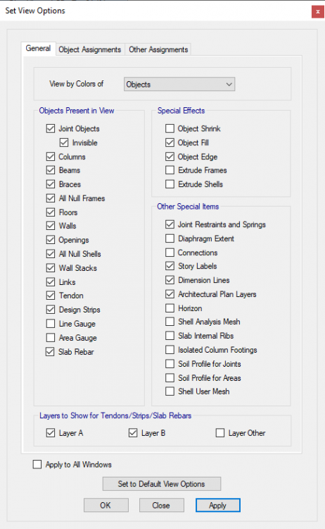
Divide option is not meant for meshing in ETABS. It is to "divide" an already drawn panel after one has changed his/her mind regarding the assignments of that element. Having said that, you can use it for meshing as well. But, it will become very cumbersome and lengthy when you want to change some assignments in divided slab elements, as you will then have to select those small panels by zooming on screen. Use meshing option to mesh the area elements. Meshing can be viewed by activating the "Shell Analysis Mesh" option from "Set View Options" tab.
-
Consult PCA notes on ACI 318; chapter 10 of PAC Notes on ACI 318-08. It is better to check them in software by considering the creep and shrinkage as well as excluding the deflections occurring before the installation of partitions.
-
-

Base fixity for column and shear wall
Badar (BAZ) replied to Abdallah123281's topic in Concrete Design
The attached information is related to design of steel structure (portal frames). This is is not related to your design. For shear wall based structures, it does not matter whether you assign fixed or pin support. Only soil-structure interaction (SSI) will change your results. The simplest way to model SSI is to use Winkler springs under the foundation. For that, you will have to model footing with shell elements and assign springs based on modulus of subgrade reaction to the bottom and side faces of foundation. If you have below grade stories, you can assign springs to your basement walls as well. The detail discussion on the subject can be accessed through these documents NIST GCR 12-917-21 Soil-Structure Interaction for Building Structures FEMA P-2091 A Practical Guide to Soil-Structure Interaction -
Use over-strength factor to magnify axial forces only. Their primary objective, in relation to seismic resistance, is to transfer axial forces as collectors or distributors as a part of diaphragm. Formation of flexural hinge is not an issue with them.


