-
Posts
518 -
Joined
-
Last visited
-
Days Won
280
Content Type
Profiles
Forums
Events
Everything posted by Badar (BAZ)
-
Please look at the section 4.4.2 of the book: Pile Foundations in Engineering Practice. Piles can drive their capacity from three sources: lateral support of soil; frictional support from soil; and end bearing. I think you are referring to end bearing only in your query. For most cases, it is the major source of strength for a pile.
-
There could be number of scenarios. For code based design, that does not involve ground motions, I do not think it will matter. May be for horizontal cantilevers, you can use it; I am not sure. If you are running ground motions (NLTHA, or some other analysis), and site is close to fault, then it can be critical for some structures depending on time history records.
-
Thanks for sharing.
-
I have nothing to add.
-
Statements are not contradictory. No, you should not details your structure as IMRF in zones 3 and 4. Terms such as IMRF and SMRF refers to the deformation capacity of structural systems after yielding; more deformation capacity is required in zones three and four.
-
Please take a time to read books chapters, papers, reports, and thesis (whatever you can get hold of ) to develop understanding. Learn to read yourself, question yourself, if you truly want to develop knowledge and understanding. Boundary elements, in a shear wall, are meant to to achieve the following primary functions: 1) ensure that the nominal moment capacity is achieved without buckling 2) to ensure that the appropriate level of ductility will be achieved In addition they can also increase the shear strength as well; this aspect has not been codified yet. If you understand above points, you should get all your answers.
-
I am not sure. Check if the fiber-based interaction diagram is sensitive to the amount of confinement in columns. If confinement is the input, then use the as-built confinement.
-
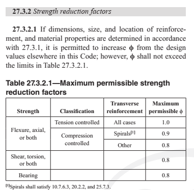
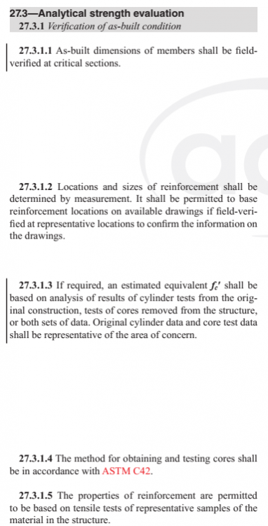
Please read the code's (ACI 318-19) chapter on the topic of "Strength Evaluation of Existing structures". I am attaching the snapshot of relevant part here. If the collected information about the structure satisfies the section 27.3 (ACI 318-19), then you can increase the strength reduction factors.
-
Roof truss deign , member length?
Badar (BAZ) replied to Muhammad SAqib shah's topic in Seismic Design
Look for any unconnected member. -

Roof truss deign , member length?
Badar (BAZ) replied to Muhammad SAqib shah's topic in Seismic Design
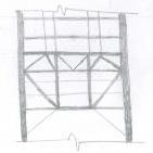
See the member in blue region. Yes, divide into segments. Find out the reason for the bottom chord members in compression; you have the model. Yes, divide into segments. -

Roof truss deign , member length?
Badar (BAZ) replied to Muhammad SAqib shah's topic in Seismic Design
Etabs gives you the reason in its design report; it is clear that your member are failing in compression. There should be a node. You are right, you need to take a closer look at your model. One of the member in your bottom chord seems to be missing as per axial force diagram. -

Seismic and Non Seismic Detailing in CSI Detailer
Badar (BAZ) replied to Waqar Saleem's topic in Seismic Design
Waslaam, Lap splices are prohibited within the region expected to develop a flexural hinge ( the region is approximately: 2 x member depth from the face of column for Bernoulli-Euler beams) to improve the post-yield deformation capacity in SMRF. This provision is there in the first code that I read (ACI 318-02); it still exists, as it should. -
The author reminds me of Taher Shah (self-proclaimed musician).
-
In ETABS, you can modify geometric properties of section either from within "Frame section property data" window, or by going trough this route: Assign > frame > property modifier. You have used the first option. When you do that, the information will not appear in "beam information" window. But you still got your property modifiers, which you can see when you go to the "Frame section property data" window.
-
If there is no error in the model, then the planted column is not the major source of design forces for the cantilever. Check which load case is responsible for the transfer of sagging moment at the end of cantilever beam.
-
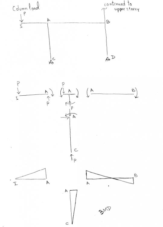
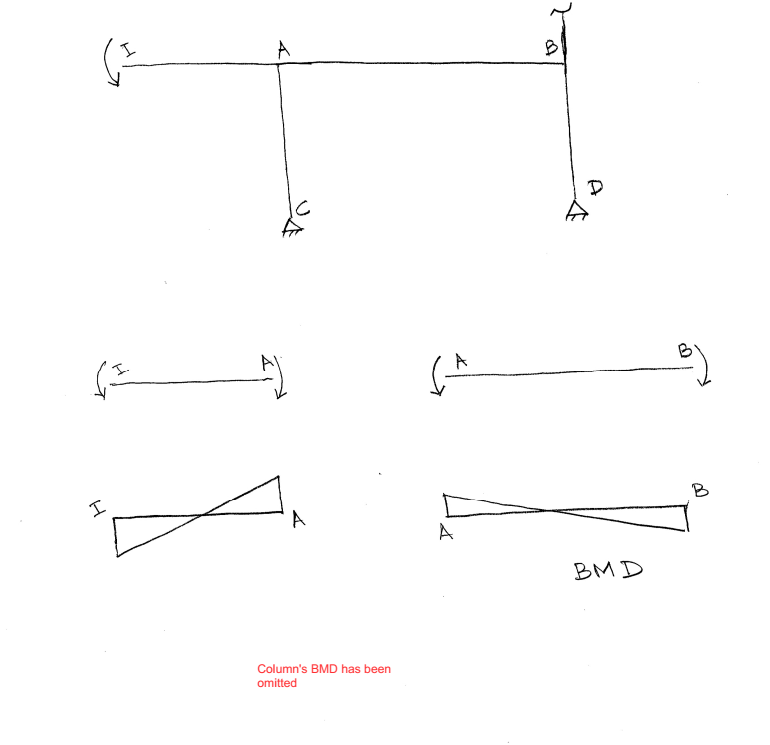
Let me break down the BM diagrams for you. The first case: High point load accompanied by a negligible bending moment transferred to the edge of the cantilever beam from the planted column. If we neglect the contribution of bending moment, we will get the following distribution of bending moment in each member. If the planted column transfers huge bending moment ( and negligible point load) at the edge of the cantilever beam, following distribution will result You are saying the you have assigned the hinge at the lower end of column, the end where it connects to the cantilever beam. If that's the case, you should get the BMD shown in the first figure.
-
It is incorrect. You cannot get the seismic information of Pakistan from UBC 97. It has been discussed somewhere else in the forum. The difference between new set of codes and UBC97, and earlier codes, is in the definition of design grounds motion parameters and design earthquake. In Pakistani code, seismic forces of structure are still based on expected ground accelerations at site; they are expressed in terms of Ca & Cv (same as in UBC 97). Since 2000, codes no longer use them, instead they have developed zoning maps in term of design spectral accelerations at short period, Sds, and 1 second, S1 (it is argued that they represent the seismic input energy better than Ca and Cv). If you want to use ASCE, you need "Sds" and "S1" for your site; these values have been reported by several researchers (take a look at the publications listed below) for different regions of Pakistan. You will also find them, hopefully, in new code of Pakistan. Probabilistic Seismic Hazard Analysis Based Zoning Map of Pakistan, Journal of Earthquake Engineering Updated earthquake catalogue for seismic hazard analysis in Pakistan, J Seismology (2018) 22:841–86
-

Etabs Mass Displacement for Accidental Torsion
Badar (BAZ) replied to Hur Hasan's topic in Concrete Design
-

Etabs Mass Displacement for Accidental Torsion
Badar (BAZ) replied to Hur Hasan's topic in Concrete Design
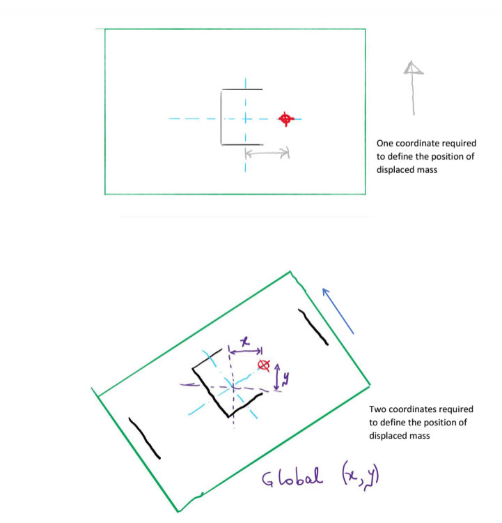
Measure the eccentricity in grid system that has members providing the major stiffness and strength. If both coordinate system has such member, you can consider displacing the mass in both coordinate systems independently. -
Yes, its enough to figure out if the tensile stresses in RC walls are exceeding the capacity of concrete to take tension, which means there will be cracks if it does that.
-
There is no beam-slab connection approach in ETABS. It can include the stiffness of flange automatically if you have defined a shell element for representing your slab, but it will calculate the required flexural rebars based on the cross-section defined for the line (beam) element. Define a T-section if you want include the effect of flange for positive-moment capacity. In that case, you need to model the slab carefully; area element with shell property can result in over-estimation of stiffness if stiffness modifiers are not applied appropriately.
-
That's strange; never noticed any such thing. Check if you read it correctly.
-

Dual System Modeled as Sway/Non-Sway?
Badar (BAZ) replied to Wajahat Latif's topic in Concrete Design
Yes, I agree. Yes! -

Dual System Modeled as Sway/Non-Sway?
Badar (BAZ) replied to Wajahat Latif's topic in Concrete Design
I have also pointed out this observation in this attached post. I have looked at its manual. Here is what I found, and which also addresses why the ETABS magnifies moments even if you set column as non-sway. ETABS split design forces in columns as M= Ms + (sway factor for amplification of forces)Mns; the component Ms is from lateral loads and Mns is from gravity loads only. Sway factor is taken as 1, as the program "assumes" that Ms comes from the P-delta analysis. If P-delta analysis is performed, the moment magnification is already incorporated in that, and there is no need to amplify moments. So sway factor is taken as 1. Once M has been calculated, the program amplifies it further by using a non-sway factor, see the attached. So, if you have used non-sway option, then this non-sway factor will be 1. But, since you have performed the P-delta analysis for drift related checks, your forces have already been amplified. -

Dual System Modeled as Sway/Non-Sway?
Badar (BAZ) replied to Wajahat Latif's topic in Concrete Design
Yes, they will be ignored. But why do you want to select the non sway option? Your design moments will not be effected much by the moment magnification factors and P-delta analysis if l/r ratio of columns is small, and if lateral drifts are also with in the limits. If you are enabling the P-delta analysis option, program will magnify your column moments anyway based on the results of P-delta iterations even if non-sway option has been selected (sway part of moment magnification equation of ACI 318 is still there because of lateral loads). One should not rely on the seismic checks performed by ETABs. Unless you have specified the actual reinforcement ( the ones in structural drawings) to the program, these results are useless.


