-
Posts
518 -
Joined
-
Last visited
-
Days Won
280
Content Type
Profiles
Forums
Events
Everything posted by Badar (BAZ)
-
The maximum seismic force that a structure can experience depends on its mass, stiffness, and damping properties.
-
1. Since we need to know the behavior of building/structure in more than one direction, we load it in more than one direction. 2. Scaling is done to limit the force that is applied on building in ETABS. 3. It is related to first point.
-
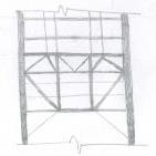
The video shows the concrete break-out failure of steel plate's connection with concrete wall . This is the case where a retrofit scheme has also failed.
- 1 reply
-
- retrofitt failure
- steel connection failure
- (and 1 more)
-

SAP2000 Problem with building deformation from seismic load
Badar (BAZ) replied to vastejzma's topic in Software Issues
I am not sure what you mean by "middle of shear wall". Shouldn't shear wall serve as the support for beams anyways? Can't comment because I am not able to understand reason for your modelling-approach. -

SAP2000 Problem with building deformation from seismic load
Badar (BAZ) replied to vastejzma's topic in Software Issues
Yes, there is something wrong with the model. I tried to check your model, but it is not responding. IN X-direction, building is exhibiting a rigid body motion above first level. You need to check your inputs related to seismic forces as well as restraints. Could it be possible that the load in x-direction has been applied at the first level only? -
Add more walls, if the forces are correct, and if your interpretation of code's provisions relating to shear strength are also correct.
-
You got it all wrong. You have to consider cracked sections in your analysis irrespective of the need for the inclusion of P-delta effects. If it is the case of compatibility torsion, then you don't need to consider full torsion.
-
Yes, you not need to consider the effect of cracking in sections. Following is an excerpt from ASCE/SEI 7-16 "A mathematical model of the structure shall be constructed for the purpose of determining member forces and structure displacements resulting from applied loads and any imposed displacements or P-delta effects. The model shall include the stiffness and strength of elements that are significant to the distribution of forces and deformations in the structure and represent the spatial distribution of mass and stiffness throughout the structure. In addition, the model shall comply with the following: a. Stiffness properties of concrete and masonry elements shall consider the effects of cracked sections." ACI 318, or equivalent guidelines, set the rules. Use manual calculations/excel sheet to investigate your beams. A single modifier can not be applicable to every x-section of beam. It better to use a low modifier for all beams (0.1 or 0.01), and then manually verify only those cross-sections who are failing the shear+torsion interaction as per results of ETABS.
-
Both practices, with and without stiffness modifiers, are followed to decide about the reinforcement requirement against the design forces. Both approaches will lead to a stable structure as long as mechanics holds. Having said that, the stiffness-modifier approach is more conservative, and is better representation of the actual conditions in most cases; one would expect columns to be less cracked than beams, and consequently will attract larger share of unbalanced moments at beam-column joint as compared to un-cracked scenario.
-
You need to use ACI 318's equation that relate service-level moment, or the moment against which you need to compute your deflection, to effective moment of inertia. The equation is 9-8 in versions before 318-14, and it is given in table 24.2.3.5 in the 2019 version of ACI . You shouldn't arbitrarily choose the factor.
-

Design of shear walls for Moment Envelop?
Badar (BAZ) replied to abbaskhan2294's topic in Seismic Design
Concept of envelope is to find maximum value of design force (shear, moment, torsion) or displacement for a bunch of loading scenarios at various locations along the member. Influence line is different. It gives you the value of force/displacement for a single point on a member for various positions of same loading type. Of course you can create envelope in this case as well. -

ETABS: Thin Shell Vs Membrane
Badar (BAZ) replied to Badar (BAZ)'s topic in Journal/ Articles/ Tutorials
If the shell element has been designated as being membrane (in-plane behavior) , ETABS will not transfer out-of-plane loads. -

Insertion Points and End Length Offsets in ETABs
Badar (BAZ) replied to Osama Anwar's topic in Concrete Design
Yes, if you are using insertion points, do not use rigid links. I am more comfortable at using rigid links. Having said that, it will not make notable difference in most situations. Unless the eccentricity is more than 9 inches and there are long spans (more than 30ft). -

Guidance with regard to the detailing of beam in seismic zone
Badar (BAZ) replied to Osama Anwar's topic in Seismic Design
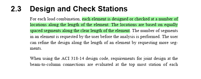
ETABS divides the region of member to report forces and perform design based on the option shown in attached screen shot. You can divide the member into different regions either by specifying minimum number of stations(sections) or maximum spacing of stations(sections). The default setting is that it will check the beam at every section located at 500 mm distance along the clear length of the member (max station spacing). See the attached screen shot of the ETABS's manual (CFD ACI 318-14) as well. -

Pure Torsional Mode as 1st Mode in Tall Building
Badar (BAZ) replied to Howard Roark's topic in General Discussion
It would have been better had you had shared you structural system as well. If you do not want the torsion as first mode, then adjust it so that center of mass (CM) and center of rigidity CR are closer. Time period of first mode looks abnormal to me. It is way more than the time period of second mode. -

Rules of Thumb for Providing Reinforcement in Joints
Badar (BAZ) replied to hali's topic in Concrete Design
Pointers: exercise your due diligence so that you have reinforcement to transfer tensile forces, resulting from rotational effects, between connecting members for foreseeable union of loading scenarios. -
Membrane does not have bending stiffness, so it is useless to apply m11 and m22. As per my knowledge, ACI 318 or other codes that I know does prescribe any modifiers for this situations. I would use 0.35 for tension and 0.7 for compression to be applied to f11 or f22. Even 0.5 is not a bad choice
-

Strong column weak beam design in etabs
Badar (BAZ) replied to Aye Min Khaing's topic in Software Issues
Etabs considers the rebar area that it suggests in calculating the capacity ratio. How else do you think one can calculate the moment capacity without considering reinforcement in members. Yes, you need to check it manually based on the reinforcement prescribed in structural drawings. -
-
In Pakistan slab on grade is normally not used as the soil is stiff and it can easily support normal occupancy loads. Use of architectural flooring is sufficient. Even if you are using RCC slab at plinth level, it should not be assigned diaphragm; this level of building will not have inertial forces because it will have acceleration values very close to that of ground acceleration. If there is no slab, there is no need to provide torsional releases. Base at the bottom of footing is fine. Fixity will depend upon number of things including type of footing, its thickness and the type of soil. If you have mat, then you can assign fixed condition. If you have isolated footing on stiff soil, and the thickness is enough to develop longitudinal reinforcement of columns in tension, fixed condition can be used.
-
You can do that. But I meant something else.
-
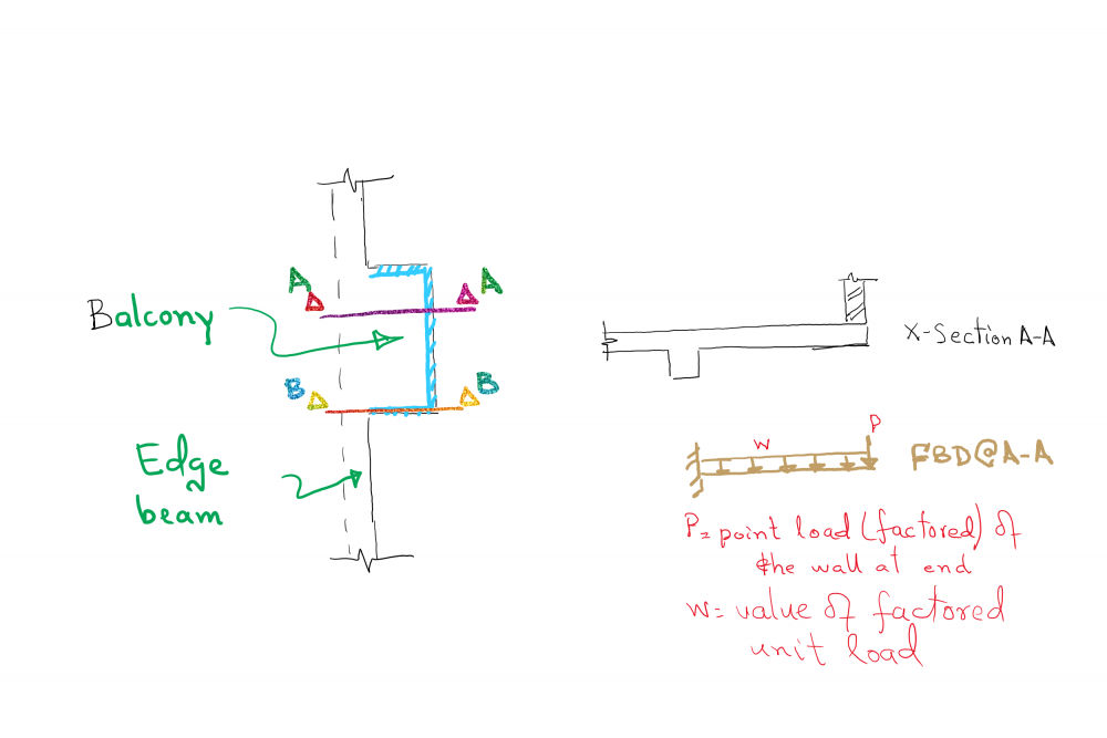
This does not mean you need beam under the line load. The line load at the end will act as point load per unit width of your balcony. The line load at sides can be treated as line for that unit width of balcony. No beams are needed,which means you will not have forces which need enlarged cross-section. Do your calculations; figure out bending moment and shear at critical section; you will know.
-
Following are the documents that you can consider for performing the PBD. You can find guidelines for hinge lengths in them as well. ASCE/SEI 41-17 Seismic Evaluation and Retrofit of Existing Buildings An alternative for seismic analysis and design of tall buildings located in Los Angeles by LATBSDC TBI guidelines for performance based seismic design of tall buildings Performance Based Design State of the Practice for Tall Buildings by EERI Nonlinear Structural Analysis For Seismic Design (NIST GCR 10-917-5) PEER/ATC 72-1 report
-
You can can take away the ability of balcony-beam to take torsion in this case as the beam is not the only load path available. However, you have to design it for cracking torsion at-least as per guidelines of ACI 318. The beam on sides and the outer end are not needed. Slab is enough to carry forces if it is normal balcony of less than 6 feet in width.
-

Adopting Eurocodes in Pakistan
Badar (BAZ) replied to Simple Structures's topic in General Discussion
It should be the personal preference in country of ours who does not have ingeniously developed guidelines. As far as RCC is concerned both codes use empirical approach for shear and torsion and empirical-analytical approach for flexure. Codes are not central as far as teaching to the students of Structural engineering is concerned. They need concepts of mechanics (statics and dynamics), theory of elasticity strength of materials, mechanics of concrete and various advance and classical methods of structural analysis. Faculty is doing extensive research of their own in Pakistan and are also aware of the research going in other parts of the world. How much of that is helpful to construction industry and the profession of Structural engineering is up for debate.


.thumb.png.b4275cf25f0183d721cf3bb17f371ae4.png)
.thumb.png.33a8db478347162036146b7cde6c200d.png)

