Badar (BAZ)
-
Posts
518 -
Joined
-
Last visited
-
Days Won
279
Content Type
Profiles
Forums
Events
Everything posted by Badar (BAZ)
-
If there is no torsion in the building, then there is no need of it being stable against torsional forces. If there are torsional forces, then you need it to be torsionally stable. It means you need to check peripheral vertical members of the building for P-delta effects.
-

ETABS: Thin Shell Vs Membrane
Badar (BAZ) replied to Badar (BAZ)'s topic in Journal/ Articles/ Tutorials
Yes, membrane behavior exist. Structural member that have exclusive membrane behavior have very little-to-no out-of-plane stiffness, and hence can only carry in-plane forces. For most structures, the choice between membrane and shell will depend on Engineer's judgement and the actual detailing of members . Well, it will also depend on weather the slab has been actually provided with the reinforcement to resist its share. -
You have said in your first post that there is a water tank below plinth level. Figure out if the water tank provides bracing to the column. If yes then adjust the unbraced length ratio of the column accordingly. You can easily calculate the K factor from the charts given in ACI code depending on whether your column is part of braced or unbraced frame.
-
IBC code use instead of UBC 1997 in karachi
Badar (BAZ) replied to kHURRAM ALI's topic in Seismic Design
There is no correlation between these parameters. Maps in UBC are based on 500 year return period (10% in 50 years), whereas as in latest codes maps are for risk-targeted earthquake having 2% probability of exceedance in 50 years (2500 years return period). UBC maps are in terms of PGA whereas now the correlation parameter is spectral acceleration. However, people have done work on this and you can get these parameters from their papers. Please get these values from following studies. Bhatti et al. 2011 Probabilistic seismic hazard analysis of Islamabad, Pakistan.pdf Ahmed 2019 Probabilistic Seismic Hazard Analysis Based Zoning Map of Pakistan.pdf -
You have wrong reasons in mind regarding this. Read the relevant literature. Look for and grab the concepts of compatibility and equilibrium torsion in code and RCC books. Stiffness factors of 0.35 and 0.01 are not related.
-
Don't assume; find out the cause. I pointed out the possibility, do not generalize.
-
The lower ratio leads to stable structure, but it does not mean that one cannot ensure stability with larger ratios. For larger ratios, you will need nonlinear analysis to ensure that. The ratio of 6 is too much, check if the ratios are correctly calculated by ETABS; it is possible that one of the displacement may correspond to horizontal members. Cantilever horizontal members will have more displacements in horizontal plane than VLLR (vertical lateral load resisting) elements and ETABS can include those values in calculation of drift which is misleading.
-
Accidental torsion: distribution of floor mass could be eccentric with respect to center of rigidity of lateral load system. You do not calculate accidental torsional, you just assume it be displaced equal to 5 percent of building's dimension perpendicular to seismic force. Drifts or displacement: drifts are displacements normalized by story heights. You will get the same result. No difference at all.
-
For RCC, seismic forces will be more than thrice as compared to wind..
-
6/5 beam to column capacity check in the last floor
Badar (BAZ) replied to Ali Karami's topic in Seismic Design
You can find it in books dealing with nonlinear analysis or the research papers dealing with "Failure mechanisms of structures with strong column-weak beam" philosophy. The idea is to enable the frame to maintain its ability to carry gravity loads when it moves into inelastic range. The formation of hinge at the top end of top story column does not inhibit the frame from maintaining its ability to carry gravity loads. -
6/5 beam to column capacity check in the last floor
Badar (BAZ) replied to Ali Karami's topic in Seismic Design
The joint at the top end of column in the top floor does not require this check. The formation of hinge at this location "is part of plan". -
Pushover and Response spectrum analysis?
Badar (BAZ) replied to Iftikhar Hussain's topic in Seismic Design
Its not a norm a norm to do both things as you mentioned. Most of the work is limited to code-based design. Nonlinear analysis is limited to only performance-based design or to do seismic evaluation of existing buildings, and even in these cases pushover is rarely is rarely used and nonlinear time history analysis is preferred over it. -
Pushover and Response spectrum analysis?
Badar (BAZ) replied to Iftikhar Hussain's topic in Seismic Design
Pushover curve will give you the capacity of your structure to carry the specified distribution of lateral forces. Checks on drifts are required while performing ESA and RSA, not Pushover analysis. You can only compare the base shear from ESA and RSA to the capacity obtained from pushover analysis. Pushover curve also gives you the ductility possessed by your structure, and that can also be compared with the ductility assumed for RSA/ESA. You should also keep in mind that the pushover anaylsis has limited applicability. -
Yes, It can be done.
-
The way forward, as far as Equivalent Static load procedure is concerned, is to use the "User coefficient" option in ETABS definition of load patterns related to seismic forces. You will need to enter the value of "Base shear coefficient" as well the "Building height coefficient". The program will multiply the "Base shear coefficient" with the seismic weight, determined by the options you defined in the mass source, to generate the total seismic demand. It will use "Building height coefficient" to distribute the Base shear along the height of the building. For RS analysis, you can import user defined response spectrum.
-
Check unbraced length ratios in your model.
-
Ground Motion Data Conversion
Badar (BAZ) replied to Engr. Muhammad Farhan's topic in Seismic Design
Fourier transform equations are used for this purpose. You can easily do it on Matlab. I am curious to know how the time domain of above three signals will look like. As all frequencies of a particular test run has the same amplitude, Fourier spectrum will be a straight line. It does not represent a real earthquake/ or real ground motion. -
You need to know cross-sectional properties and the unit-weight of the material, and the masses that are not related to self-weight.
-
UBC 97 Response Spectrum Seismic Provisions
Badar (BAZ) replied to Ahmed Waqar's topic in Seismic Design
Yes, you need to scale down. -
Thank you. The joint of top story, or the joint in which column does not extend.
- 4 replies
-
- 1
-

-
- beam-column joint
- sefp consistent design
- (and 1 more)
-
Strut-&-Tie Modelling in SAP2000
Badar (BAZ) replied to Shahzad Khan's topic in Spreadsheets & Softwares
ACI 318 has dedicated entire chapter on this topic starting from its 2014 edition. Before that, the topic used to be in the appendix of the said code. ACI also a document that can help one use the theory by looking at the solved examples of few scenarios (SP-208: Examples for the Design of Structural Concrete with Strut-and-Tie Models). -
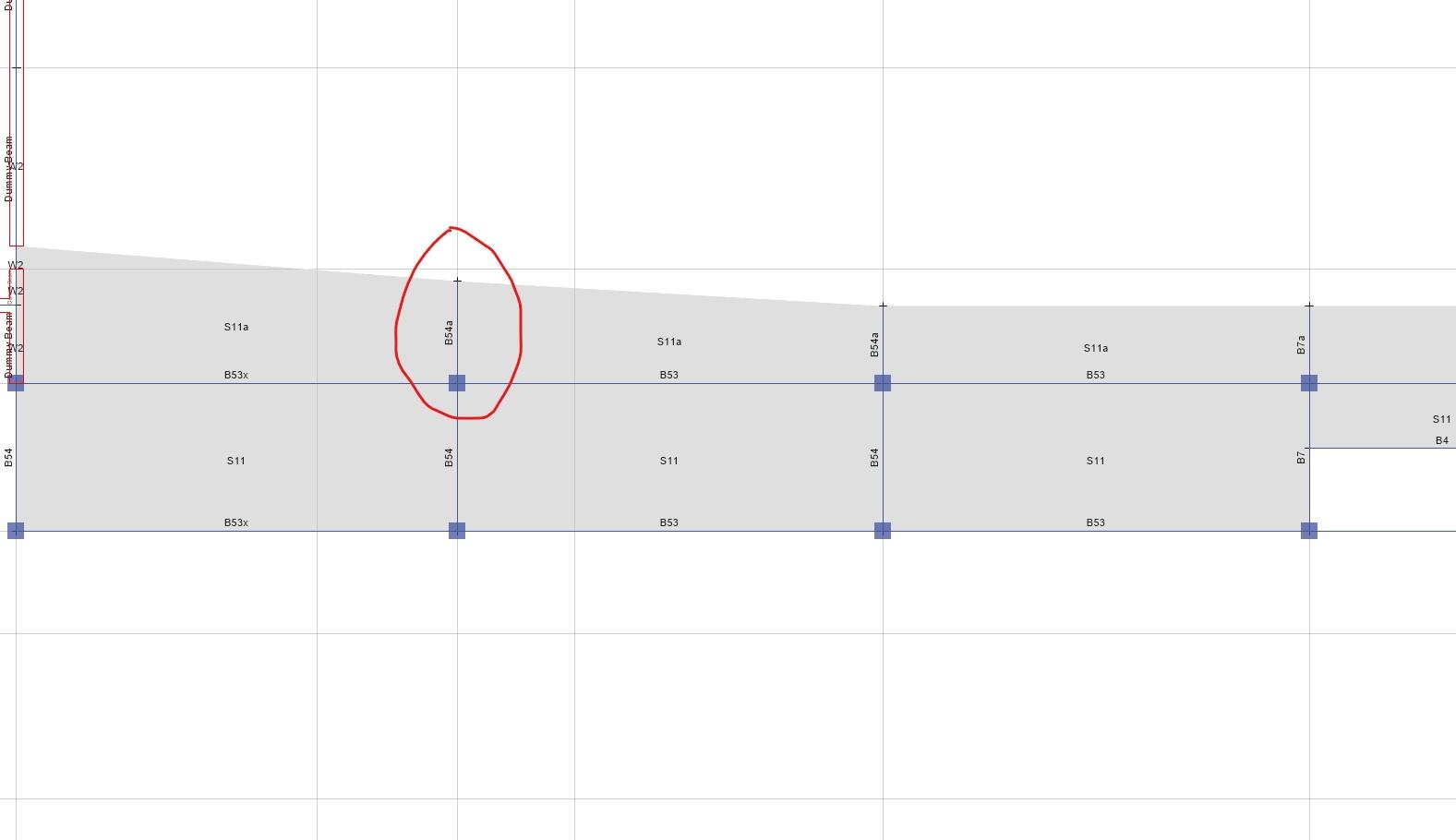
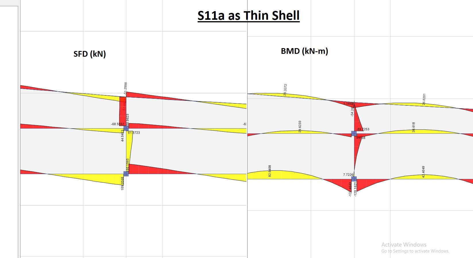
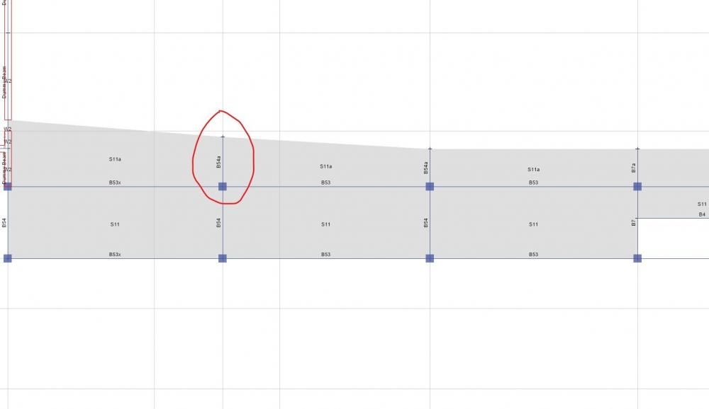
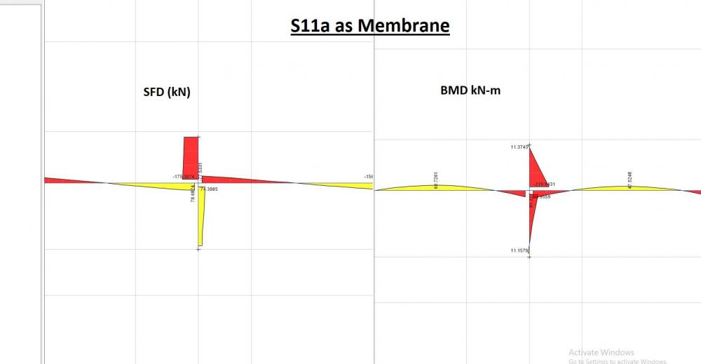
Young engineers often ask about whether to select membrane or thin shell or thick shell for modelling area elements such as RCC slab. I am going to talk about the difference in the results when choosing thin-shell or membrane. This is what makers of ETABS says about the topic. I will quote the following to clear out the structural difference between the two: "Load which is applied to membrane objects transfers directly to supporting structural objects, whereas meshed shell objects have bending stiffness and therefore resist a portion of the load through flexural deformation. As a result, less load will be available to transfer to beams located under a shell, while 100% of the load will transfer through a membrane". Lets see how much can the results differ. Figure below shows the partial framing plan of a level in the building I will discuss how the modelling of S11a as thin-shell or membrane will effect the design shear and moment on the beam B54a, see figure above. The figure below shows the design forces obtained against the gravity loads for the membrane case: The figure below shows the design forces obtained against the gravity loads for the thin-shell case: Based on the results presented above, B54a's design shear increased by 155%, and its design moment by 147% as compared to S11a's behavior as membrane. Now the question, that a Structural engineer needs to ask is: Which result is more appropriate or which result captures the actual behavior more realistically? And that is where you engineering judgement comes into play.

-
Check following: Design code assigned in the software RCC design manual of the software and find how it calculates this for the design code of your interest If you still reach at the same conclusion, ignore these results. The software can do that because of some bug.
-
The lower one is not used for footings by practicing engineers. The reason: area element (Slab) has more options to redistribute the load then the line element (beam).
-
Moment Capacity of retrofitted section
Badar (BAZ) replied to Fatima Khalid's topic in Concrete Design
One way will be to use sections designer in CSi softwares (Sap 2000, ETABS, Csi Col). Model four angles with re-bars by locating them at the centroid of of angles. You will have to define material for that reinforcement. This will be in addition to the existing reinforcement in the cross-section You can easily calculate the moment-capacity provided by four angles by manual calculation keeping in mind the crushing strength of concrete, and add it to existing capacity.