-
Posts
578 -
Joined
-
Last visited
-
Days Won
138
Content Type
Profiles
Forums
Events
Everything posted by Ayesha
-
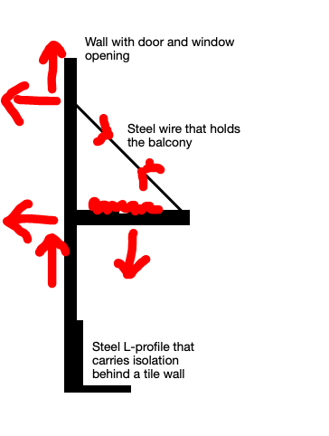
Before I reply, just to make sure I understand your question and sketch right. You said that "The concrete wall has a frontpart consisting of isolation and bricks." 1) Is this brick wall self supporting or connected to concrete wall through some anchors? 2) The gap you show in the above sketch, is that isolation? To answer your question, 1) The balcony has self weight, weight of finishes as well as live load for which it needs to be designed. These loads will be transferred through the connection of balcony beam to the wall as well as through the steel wire. The very important this to notice is that due to the arrangement of balcony support system, your balcony beam will also have an axial load. I have marked the reactions. First step is to resolve the forces as reactions on the connection to the wall. This also requires checking the steel wire to make sure it has enough strength as well as the balcony beam and its connection to wall. Once you have done that, then you need to transfer the load (reaction of the balcony) to the foundation through the wall. If the wall is not connected to the concrete wall below, then you need to analyze the wall for this load and make sure it has enough flexural and shear strength to transfer this load in combination with other environmental loads like Wind and Seismic etc. it depends on how you are analyzing the wall. If you are using a software for example ETABS, you can model the openings in the software and design accordingly.
-
I would suggest buying a handbook from Amazon.
-

CSIXCAD Drawings and Scheduling In ETAB
Ayesha replied to Shahzad Khan's topic in General Discussion
If the bar lengths are long, you need to splice them and depending upon your seismic detailing, as also correctly pointed out by Kamranullah, you need to pick a splice location. -

Connection between wall and slab of ground floor
Ayesha replied to Kirill's topic in Concrete Design
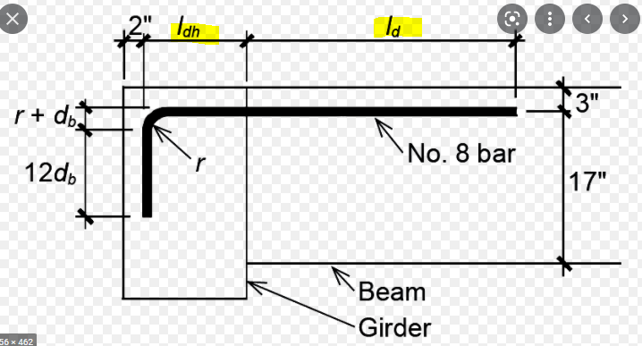
You should bend them and the length should be equal to development length of a hook. Below is the concept: Normally, the width of wall should be kept enough wide that you are able to achieve the ldh length and from the face of the wall you need to extend the rebar a distance of ld. You can find the values of Ldh also called development length of hooked bar and ld - development length of straight bar in your Russian code. For US Code, you can use this link: https://structuralcalc.com/rebar-development-length-calculator-to-aci-318/ If you extend your wall bars a distance of Ld from the face of the wall, you need to just place the slab/ beam bars to the end as your wall reinforcement which is bent will take of of flexural moment at end of slab. No need to connect or anything.. Just extend your slab bar to the end of wall horizontally using a straight bar. This can also be correct because in houses the loads are small and if you aren't in seismic zone, and the design is over-reinforced the development lengths can be reduced. Also, not bending the wall reinforcement into slab means that your slab will have more positive moment. Nothing is wrong with this approach. -
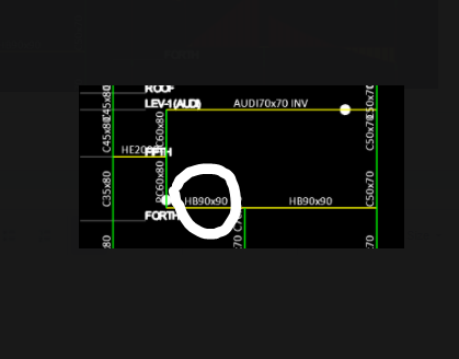
This is a roof beam and the criteria should be same as all roof beams. You can follow recommendations of ACI-318 based on the version you are following. See this: https://wiki.csiamerica.com/display/kb/Nonprismatic+frame+objects Yes it will and the software will consider this.
-

Floating Column Design / Pick Up Column Design
Ayesha replied to M.Salman's topic in Concrete Design
It gives because there is force there that requires the reinforcement. You should look at detailing of the column and the respective boundary conditions associated with it. If the floating columns are not part of lateral force resisting system, then check if it is attracting lateral load. Some thing to consider. -

Load combinations for shallow or deep foundation sizing
Ayesha replied to callmeismail's topic in Foundation Design
Yes. This is controversial and I have seen it being used and also not being used. Normally you need to see the local building code. I recently did a project in California and they are using it there. Yes, everything. Yes, for seismic loads, all effects should be there including vertical. -

Steel pedestrain bridge connecting two buildings
Ayesha replied to Nasreen khushi muhammad's topic in Steel Design
Nasreen, For your question: You need to do analysis for the bridge considering environmental loads like snow, wind, seismic, and dead load with pedestrian loading and see if this will be okay or not. What is the basis of your design? How are you designing this connection. What limit states are you checking. -
Waqar, For vertical spring values, you need to know deflection of your piles. That is obtained by first calculating load per pile, and calculating the deflection using geotechnical recommendations. Once you have load and deflection of a single pile, you can calculate the spring stiffness by load/ deflection. This is based on un-factored loads. For lateral spring values, geotechnical should provide you the values or lateral k values and you should consider pile group effects. See this discussion:
-
Baz has put it well. You need to identify your collectors and design those for overstrength LCs. Most likely the beams connecting to shear wall will fall under this. Also look up your the code and see what it says. For Steel AISC 360 is very clear on which members to use over strength.
-
HI Ayman, Can you please provide background on your question. Just out of curiosity, why can't you just model your building in a structural analysis program and get the results. Why do you need to use Shear Beam Model Assumption.
-
The standard loading is Dead, Super-dead, Live, Wind, Seismic, and any maintenance loading. Loading is related to the "use of structure". You can apply load based on use based on ASCE 16.
-
You need to know the footprint of the load and then you can apply it as a point load or an area load depending on if you are using Line Elements or say using shell elements for culvert.
-
First, I need to understand your question. Is this the cantilever beam that you are talkin about. See snapshot below and confirm. What does this statement mean - "Whenever I release the moment value of column from the bottom side it will take proper action of beam." What is proper action of beam? Does this statement mean your axial load goes away? That is why I am emphasizing that you figure out the "load case" not "load combination" which is causing this trouble and also why releasing moment is removing axial load, doesn't make sense. Where is the axial load diagrams? Can your first please explain in detail.
-
Did you do a breakdown to see which load case is causing this? Normally I check the the governing load combination, then run each load case separately of the governing load combination to see what is contributing the most. If you have already done it, can you tell us which load case is causing this big axial load and then after identifying the problem we can suggest a solution. Is this structure steel or concrete?
-
This might help. Contact the forum participants too especially Imran !
-
I haven't seen this design, maybe its more common in "middle east" etc. To me it looks bad, just because if the base is concrete, it will have very tight design requirements on water tightness (as also mentioned above) but also because the underside of foundation in touch with the ground or the sides exposed to sun will result in significant shrinkage demand on the foundation. Might be better to use steel tanks. Just saying.
-
The leak is because of poor welding/ inadequate steel design between the steel base and steel tank walls. I am assuming your tank is not just walls and it has a base. Get a welder to fix it and do seal welds if angles are used on the inside of the base.
-

Importing ETABS file from v19.1 to v18.1
Ayesha replied to Muhammad Hashmi's topic in General Discussion
So this solution worked for you? -
Do the design manually. Buy a book, spend time understanding it and follow examples.
-

Help with a confined masonry intervention / rehab
Ayesha replied to jcvaldes's topic in General Discussion
Your reasoning is good. Structural Rehab is nothing different than new design, just a few additional shenanigans to cater for. I personally like the idea of providing new framing (see below for details) if you can for two reasons. 1) Confined masonry beams would be very weak, and reinforcement in them might not be what you will need to justify a seismic load resisting system. This point is in-terms of ductility requirements that are assigned to different category, like if your frame ends up being an Intermediate Moment Frame (for example), are you confined masonry beams / false beams detailed to give you that ductility. The answer is probably not, so technically speaking, if that is the case you can't rely on them. 2) You have to think of the structural retrofit in-terms of Lateral Force Resisting System (LRFS) and Gravity Force System. In order to keep the footprint small, it might be better idea to introduce new shear walls that can be connected to floor diaphragms and that can take all the lateral load to foundation, provided, you can provide such shear walls, connected to floor slab and also pour new foundations for them and then your existing system can stay light assuming collector design doesn't poses an issue. If you connect them as simply supported, then they will only help with gravity. One thing as a heads up that, if you are attaching steel beams to concrete columns (post install), the anchors might not be sufficient as I am not aware of the code you are following but say in US, Seismic Codes require beam to column connections in ordinary moment frames to be designed for most probable moments which for post installed steel to concrete connections would be impossible to meet. Hope this helps. -

Help with a confined masonry intervention / rehab
Ayesha replied to jcvaldes's topic in General Discussion
Why do you want to reinforce these beams? Also, I am not sure that I understood your post well. You are referring to these beams as false beams. Why do you call them this? Regarding your idea to reinforce this concrete beam, just placing a steel beam under concrete beam will not transfer any shear from Concrete beam to Steel. The two beams act independently. However, the lateral resistance of frame will increase and that will result in your frame attracting more lateral seismic load than before as stiffness of frame will increase and stiffness attracts load... Doesn't look like a good idea. Do this if you can justify the retrofit and also if you can accurately quantify the effect. -
There are already a lot discussions on Brick Masonry on this forum. ETABS is not suitable for brick masonry design.
-
Bijay, Welcome to the forum.


