Search the Community
Showing results for tags 'Deflection'.
-
I am trying modelling a simply supported plate model in with 10×10 mesh with density 25 Knm2 and E2510^6 and comparing it with results of other finite element applications and also with numerical matrix analysis by hand calculations. Both fem app and hand calculations results match but those of csi bridge and staad pro doesn't though they matched with each other. I was sure of correct modelling and also checked for equilibrium each time, I tried models of other dimensions l b and h as well. Each time fem results and hand calculations matched perfectly. For example I tried modeling 35×50 m plate with 2m depth. Hand and fem calculation results were 30 and 33 mm at centre resp. But csi bridge and staad pro for same parameters gives 230mm. For other models also the result are far too variable like this case only. Please I need urgent support. Any reference would be appreciated. Also how come two fem applications give these absurd results for exact same parameters?
-
-
Hi All,How to calculate the short term horizontal displacement (with adopting cracked section of the concrete) on free standing wall with eccentric footing at bottom, which is subjected to wind pressure alone. This is same as calculating torque of cantilever wall. This is a plot boundary wall with eccentric footing. Thank you
-
Assalam o Alaikum, I'm facing a problem related to the analysis of PT slab in etabs. After adding tendons in column strip the -ve deflection is increasing instead of decreasing. This is my first time that i'm doing PT slab analysis on etabs. So, i might be missing something. Please help me out. I'm checking deflection on combo of PT-FINAL + DEAD.
- 3 replies
-
- post-tensioned
- slab
-
(and 1 more)
Tagged with:
-
While checking the allowable deflection in member in ETABS, which deflection is to be considered, absolute or relative? Which one represents the actual deflection of the member?
-
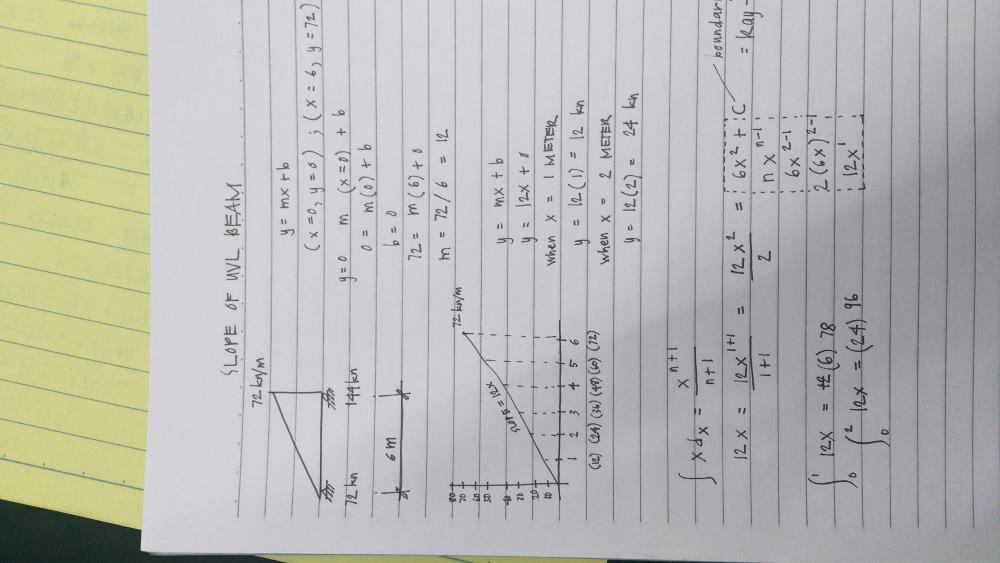
I am currently doubting what our professor is teaching regarding this topic. He said, in order to find the slope of a UVL beam we would have to use the "y = mx + b". I found it odd that he used the force given as a coordinate in the cartesian plane. Is his process correct? Can someone please tell me? (Kindly see photo attached)
-
My ETABS model does not show deformed shape on dead loads and any combo having a dead load. I model it about a month ago and it was showing deformed shape but I don't know whether I change the setting somewhere in ETABs or another issue. It shows deformed shape on live loads Please, I need help.
-
Do etabs or sap has allowable deflection checks for beams if it is analysed and designed through these softwares.
-
Aoa I have a question? if I want to check deflection for beam manually so I have to consider it as T or Rectangular beam for deflection check OR first, I have to check whether beam act like T or rectangular beam (a<hf) ??
-
Hello, While I was modeling a 20 story building with symmetrical concrete slab sections and loads in each story, I noticed that the deflection of the slab increases the more I go higher in elevations despite having the same sections, dimensions and loads. I know that floors with symmetrical shapes and loads must endure the same stresses so it has the same reinforcement. Can someone explain this behavior or explains why it occurs if I was wrong ? Thanks in advance
-
-
- mechanics of solids
- lectures
- (and 7 more)
-
Assalam o alaikum, For assuring deflection check of flexural members, we compare immediate deflection due to live load with L/180 or L/360. Also we compare total deflection (sum of immediate deflection due live load and long term deflection due to "dead +sustained loads") with L/240 or L/480. These deflections are calculated using corresponding effective moment of inertia "Ie" using equation 9-8 of section 9.5.2.3. To find out immediate deflection due to dead load we find out it using Ie calculated using cracking moment due to dead loads. To find out immediate deflection due to sustained loads we find out it using cracking moment due to sustained loads. To find out immediate deflection due to D+L we find out it using cracking moment due to dead + live loads. But to find out immediate deflection due to live load, we don't find it using cracking moment due to live load. We find out it by the difference of deflection due to dead + live load with the deflection due to dead load only. as shown by following results of manual calculations (Results from example 10.1 of PCA notes of ACI 318) Del.dead = 0.098 in (calculated using Ma due to dead load only and corresponding Ie came out to be 10648 in4 = i.e. Ig because Ma is less than cracking moment) Del.live = 0.0744 (calculated using Ma due to live only and corresponding Ie came out to be 10648 in4 = i.e. Ig because Ma is less than cracking moment) Del.(dead+live) = 0.344 in (calculated using Ma due to dead+live combo and corresponding Ie came out to be 5345 in4 < Ig because Ma is greater than cracking moment) Note that 0.344 is not the simple sum of 0.098(Del.dead) + 0.0744 (Del.live) because here for Del.live, Ie used was based on live only i.e. Ig =10648 in4; for Del.dead, Ie used was based on dead load only i.e. Ig = 10648 in4; and for Del.(dead+live) Ie used was based on (dead+live) load combo i.e. 5345 in4. All three "Ie" are different". My question is, how to cater this in etabs modeling because in etabs it simply super impose deflections due to dead and live for D+L combo which must not be the case. More over, does modifier 0.35 is enough to cater effect of effective moment of inertia? Thanks.
- 2 replies
-
- deflection check
- minimum thickness
-
(and 2 more)
Tagged with:
-
I work in a project with large spans (9.2m X 8m) and large service loads (4kn/m^2 SDL+Partitions), (7.5kn/m^2 Live load) In modeling the project on ETABS I set the property modifiers for slab (thin shell as 0.25) and this affected the deflection in slabs ( about 5 cm deflection from service loads) Hence: Slab thickness is 22 cm and interior beams 50X50 and the owner didn't allowed to increase the thickness Any suggestions to solve the problem.
-
This particular slab (19x18 ft) is expereincing too much displacement, giving rise to very close spacing in slab panel in the middle strip. It has three interior beams placed to carry line load of the walls above. How can this displacement be reduced? Slab 19x18.bmp
-
Hi, I have a problem with a simply supported deep beam which has a uniformly distributed load. The beam is simply supported at both ends but I have to consider the results for the following 3 scenarios - where the support is at the bottom of each end of the beam - where the support is at the mid point at each end of the beam - where support is at top of each end of the beam I have run this using FEA and I'm finding significantly different deflections and stresses when the beam is supported at the midpoint at its end and the other two scenarios...can anyone explain the exact reasoning for this? Sincere thanks Daniel
- 7 replies
-
- deep beam
- deflection
-
(and 2 more)
Tagged with:
-
1-how to calculate deflection for a t-beam? 2-will it be different from the rectangular beam? 3-will concrete strength effect the deflection?
- 4 replies
-
- i beam
- deflection
-
(and 2 more)
Tagged with:


.thumb.jpg.700916fbc7ead330085e15745d0270bd.jpg)
