Search the Community
Showing results for tags 'analysis'.
-
Abstract This research project is aimed at analyzing the mortar of the historical Ramkot Fort in Azad Jammu and Kashmir (AJK), Pakistan and designing a modern day compatible mortar for its restoration. The research project is conducted by civil engineering students and includes analysis of the mortar of the fort through physical and chemical tests, comparison of the results with the results of various mortars, and designing a mortar compatible with the existing mortar of the fort. The physical tests include the sieve test, water absorption test and compressive strength test, while the chemical tests include the X-ray fluorescence test, X-ray diffraction test, and the Scanning Electron Microscope-Energy Dispersive Spectroscopy test. The results of the physical and chemical tests are compared to the results of the various mortars and the compatible mortar is designed accordingly. Introduction Ramkot Fort is a historical fort located in Azad Jammu and Kashmir (AJK), Pakistan. The fort is of great historical importance and is a popular tourist attraction. The fort is in need of restoration and preservation due to its age. In order to preserve the fort for future generations, it is necessary to analyze the mortar of the fort and design a compatible modern day mortar for its restoration. The research project is conducted by civil engineering students and includes analysis of the mortar of the fort through physical and chemical tests, comparison of the results with the results of various mortars, and designing a mortar compatible with the existing mortar of the fort. Methods The mortar of the fort is analyzed through various physical and chemical tests. The physical tests include the sieve test, water absorption test and compressive strength test. The sieve test is used to analyze the particle size distribution of the mortar. The water absorption test is used to measure the porosity of the mortar. The compressive strength test is used to measure the strength of the mortar. The chemical tests include the X-ray fluorescence test, X-ray diffraction test, and the Scanning Electron Microscope-Energy Dispersive Spectroscopy test. These tests are used to analyze the composition of the mortar. Results The results of the physical tests show that the mortar of the fort has a particle size distribution of 0.5 to 4.5 mm, a porosity of 17.8%, and a compressive strength of 19.2 MPa. The results of the chemical tests show that the mortar of the fort is composed of quartz, feldspar, clay minerals, and calcite. Comparison The results of the physical and chemical tests are compared to the results of the various mortars and the compatible mortar is designed accordingly. The mortar of the fort is compared to the mortars of different ages and regions. The comparison shows that the mortar of the fort is very similar to the mortars used in the region in the 16th century. Conclusion The research project has successfully analyzed the mortar of the historical Ramkot Fort in Ajk, Pakistan and designed a modern day compatible mortar for its restoration. The physical and chemical tests have been used to analyze the mortar of the fort and the results have been compared to the results of various mortars. The compatible mortar has been designed accordingly. Comments The research project has successfully analyzed the mortar of the historical Ramkot Fort in AJK, Pakistan and designed a modern day compatible mortar for its restoration. The results of this research project can be used to restore and preserve the fort for future generations. References 1. National Monuments of Pakistan, Ramkot Fort https://pakistanmonuments.com/ramkot-fort/ 2. Ali, M., Tahir, M. N., & Iqbal, M. (2016). Characterization of ancient mortars in the fort of Mughal period. Construction and Building Materials, 112, 902-911. 3. Khan, H., & Khan, A. (2016). Characterization and Testing of Mortars Used in Historical Buildings of Pakistan. Journal of The Institute of Engineers Pakistan, 67(4), 29-40. 4. Khan, M. A., & Khan, N. (2018). Physical and Chemical Analysis of Ancient Mortar of the Monuments of Pakistan. Asian Journal of Civil Engineering (Building and Housing), 19(6), 763-781.
-
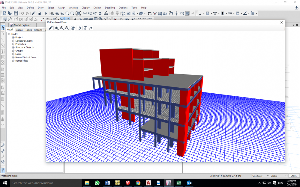
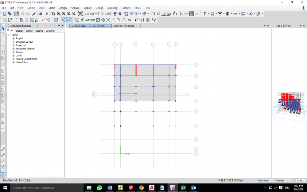
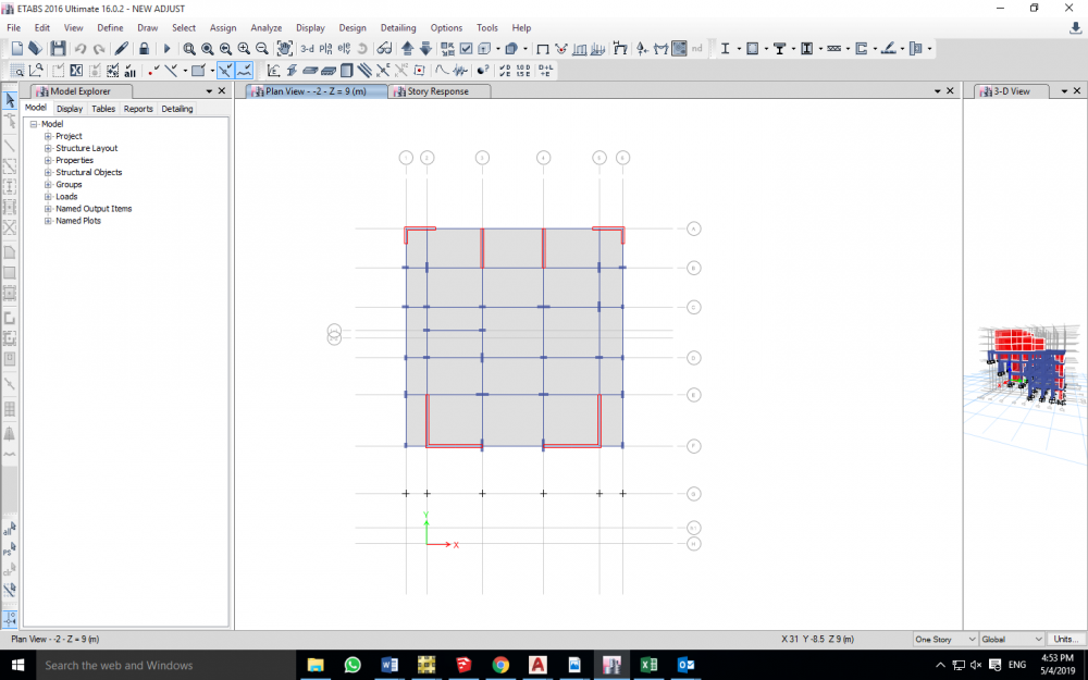
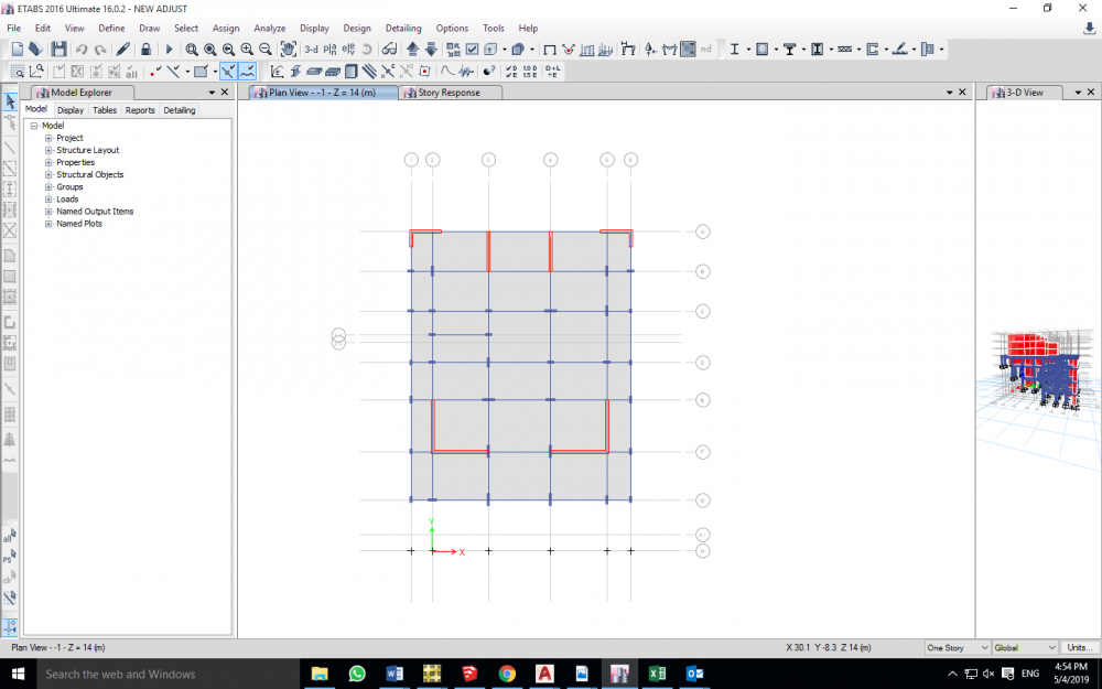
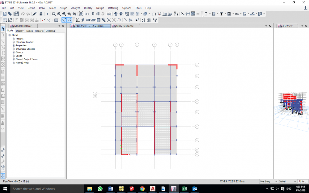
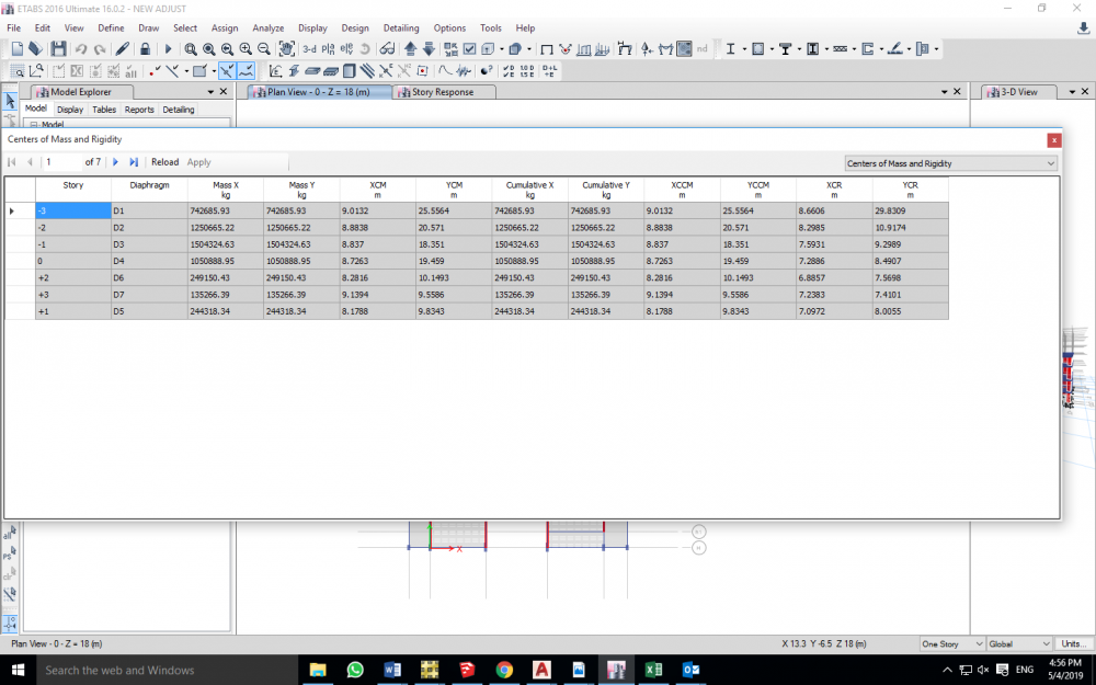
Hello Engineers So I'm having this 7 story building on a sloped land, the occupied levels will be from zero level (Street level) to +3 level , 4 residential stories. the bottom three -3,-2,-1 are being constructed on three levels in order to avoid drilling and any excavation work, considering that building is on hard rock (top of a mountain), and it will be very costly in order to do so. there are many problems that I have Encountered, and I truly need the help from you guys. -the first one is that the occupied stories's structural system is a load bearing walls, rested on Dual system of shear walls and moment resisting frames(the bottom three stories) and now I am Having soft stories , is it correct to model brick walls in the model, as they participate in their stiffness, and if modeled and still there is a soft story, what should I do? as you can see from the figures, the story geometry, specially -3,-2, is way less than that upper floors, and I can't go much deeper downwards in order to increase the number of vertical element. -in the 3 bottom levels+ zero level, Center of mass and center of rigidity are way far from each other, "way more than 5%L", which eventually causes Extreme torsional irregularity, More than 1.4 max drift to avg displacement values are obtained when checked to static load cases, I even Added the two shear walls at the top of the plan on order to pull center of rigidity closer to center of mass, But still, No point of that. I once heard from an Engineer, that Even if the building has torsional irregularity, when you design Piers and columns using Etabs, the program already takes care of that irregularity, as much as I want to believe that, But I think that torsional irregularity is a matter of a hole building geometry and behavior Plus it's a code requirement , and increasing the area of reinforcement won't help, what's right and what's wrong ? -is there any other checks that I should Do ? , is there any recommendations/Suggestions ? **I would truly Appreciate Your help. thank you.
-
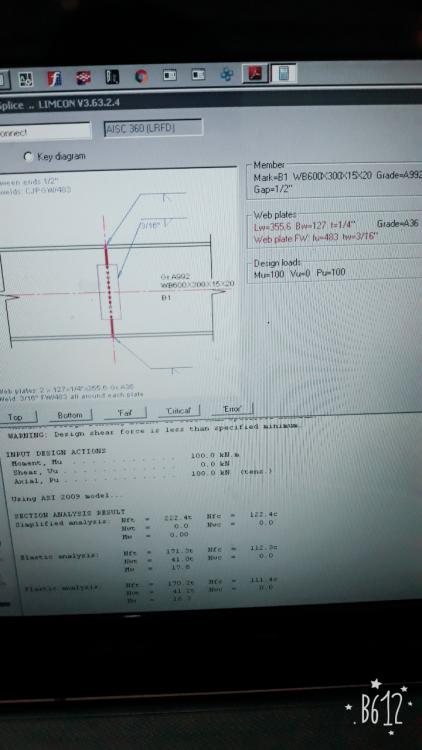
Hello there SE Pakistan, Im designing welded moment splice connection using Bentley LIMCON, and i found these kind of SECTION RESULT ANALYSIS on the report, There are this simplified analysis, elastic analysis and plastic analysis. I just wanna know how do you calculate required load in elastic analysis and plastic analysis??? Cuz i figured it out how to calculate it with simplified method, to find the nft(flange tension) using Mu/(d-tf) + 1/2Pu and nfc(flange compress) using Mu/(d-tf) - 1/2Pu, because on the other result (elastic and plastic method) they gave me significant different result.
-
I am designing a 10 storied industrial building . Architect used a slanted wall in the front elevation of the building for aesthetic reason. But for structural framing I need to model this shear wall in ETABS. Is is possible in ETABS or I have to use any other software?
- 6 replies
-
- modelling
- building design
- (and 6 more)
-
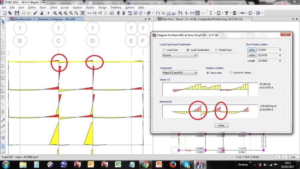
I am just starting with the structural design using ETABS. So that makes me curious if something unusual happens. I have attached a screenshot of my analysis of a beam. It shows that I am having positive moments at support from one side of a support, whereas negative at the other side(which is usual) for the governing design combo. I am just unable to perceive positive moments at support. Just posting it so that members can help me if this is usual or have I done something wrong while modeling. Looking forward for responses.
- 3 replies
-
- concrete design
- analysis
-
(and 1 more)
Tagged with:
-
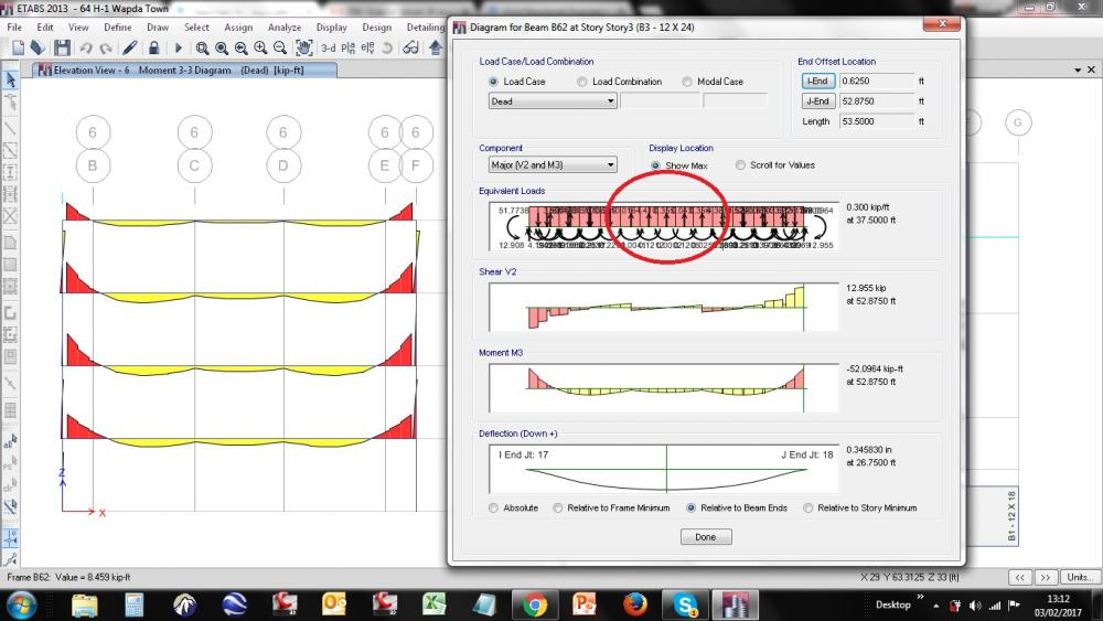
I just had an analysis review of a three storied moment resisting frame structure. While analyzing a continuous beam supported on another beam, I noticed that the equivalent loads show in upward direction rather than downwards(as can be seen in the attached snapshot). The shear and moment diagram seems to be fine though. I know that I messed up with the meshing which has messed up the drop of the loads but should it also mess up the direction of the equivalent loads? Or is it that I am looking at the problem from a wrong way? Please help me in this confusion.
-
- equivalent loads
- etabs
-
(and 1 more)
Tagged with:
