Search the Community
Showing results for tags 'b/c ratio'.
-
Is there any way we can modify the analysis results from etabs by some factor and use those modified values in design?
-
Dear seniors! can we ignore column to beam capacity ration in top story. i am designing a eight story commercial building in seismic zone 2b.
-
Dear, How to check beam-column joint & strong column-weak beam in Etabs? Thanks in advanced Rifat
-
i want to know if it is mandatory to check 6/5 beam to column capacity control in the last floor of the building. because in the last floor, the joint only has one column and normally two beams and it is hard to satisfy this issue. you will need a bigger column (in size or reinforcing) compared to below floors. is there any exception for the last floor? (working with ACI)
-
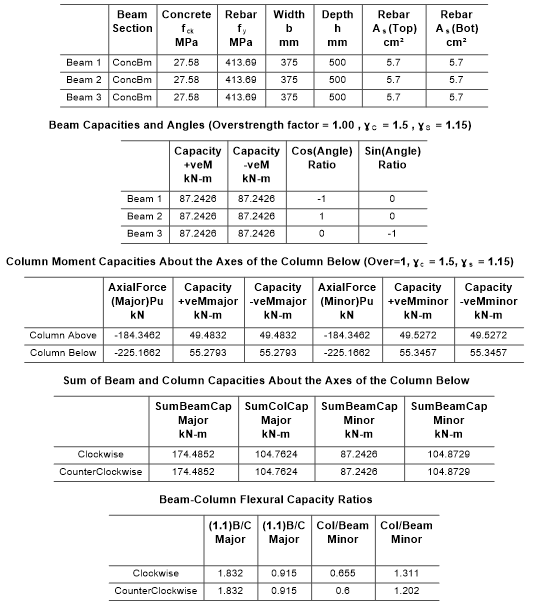
how to check beam/column capacity in etabs? what are the limits for the ratio? any reference to the literature?
- 20 replies
-
- b/c ratio
- beam/column capacity
-
(and 1 more)
Tagged with:
-
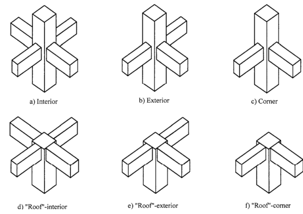
*SEFP Consistent Design**Pile Design**Doc No: 10-00-CD-0007**Date: April 16, 2018* 1.1. FUNCTION OF JOINT Beam-column joint must transfer the forces, such as moment, shear and torsion, transferred by the beam to the column so that the structure can maintain its integrity to carry loads for which it is designed. Another function of the beam-column joint is to help the structure to dissipate seismic forces so that it can behave in a ductile manner. 1.2.WHY DO WE CARE During an extreme seismic event, the code-based structure is expected to maintain its load-carrying capacity for gravity loads even after the structure deforms into inelastic range so that it does not pose any life safety hazard. Hence, the joint can go through significant degradation of strength and stiffness, and if it fails in shear, or anchorage, the life-safety objective of code cannot be achieved. 1.3.CONSEQUENCES OF FAILURE 1.4.THINGS TO CONSIDER FOR BEAM COLUMN JOINT Longitudinal bars of beams, or slab, must be able to develop their yield stress, so that the beam/slab can transfer moment to joint. It means that longitudinal bars must have adequate development length for hooked bars. This implies that the size of the column must be such that bars can develop their tensile forces. If bars can transfer moment, they can also transfer shear as far as monolithic construction is concerned. The shear strength of the joint must enable the transfer of moment and shear through it. The joint should be Constructible: Congestion of reinforcement is the main concern. 1.5.DESIGN SHEAR FOR BEAM COLUMN JOINT The design shear for beam-column joint depends upon the relative strength of beam and column at the joint. For the joints part of the special moment resisting frame, the shear force will be the one that corresponds to the development of hinge in the beam because the frame is required to satisfy strong column-weak beam criteria. If it is a knee joint, then joint area must resist the shear equal to the development of tensile force in the beam. The tensile force will be equal to the product of the area of tension steel, yield strength and the factor that represents the overstrength of steel rebar. If it is not a knee-beam-column joint then, the design shear of the joint will be algebraic sum of tensile force in the beam and the column shear. The column shear is the one that is required to keep the joint in equilibrium, i.e the shear corresponding to the development of the probable moment capacity of beams at the joint. For the joints not part of the special moment resisting frames, one needs to investigate whether the beam or column will yield first. For knee joint, if the column is weaker then the beam, the tensile force cannot exceed the moment corresponding to the development of hinge in column 1.6.THE JOINT: Definition and classification Portion of column within deepest beam that frames in to the column (ACI 352-02). ACI 352-02 categorizes joints based on the displacement-demand imposed by connected members. · TYPE 1 (Section 2.1.1 ACI 352-02) These joints possess limited ductility, and hence the connected members are designed for limited ductility. They are used in situations where ductility of structure is not a concern. · TYPE 2 (Section 2.1.2 ACI 352-02) These joints connect members which designed to have sustained strength under large deformations. Joints are also classified based on their location in framing system 1.7.THE JOINT: Design forces The joint is designed for the shear that results from attainment of the flexural strengths of members connected at the joint for type 2 joints. For type 1 joints, same principle is employed, unless the both members are overdesigned and the engineer does not expect both members, i.e. beam and column, to yield under design forces. 1.7.1. FLEXURAL STREGNTHS: TYPE 2 No strength reduction factor is used for computation of flexural strength. Steel stress is multiplied by factor of 1.25 for computation of flexural strength (3.3.4 ACI 352-02). For type 2 joints, the flexural strength of beams needs to be calculated only, as we do not expect the hinge-formation in columns; we will proportion the beam-column assembly of this joint as per strong-column-weak-beam approach. The slab reinforcement within the flange of beam must also be considered for computation of flexural strength of beam if the slab is integrally cast with beam and if the longitudinal reinforcement of slab is anchored (3.3.2 ACI 352-02). For interior connections, and for exterior and corner connections with transverse beams, the portion of slab to be considered as flange should be as per guidelines of section 6.3.2 of ACI 318-14. The effective flange width should not be taken less than 2 times the width of beam. For exterior and corner connections, without transverse beams, the effective flange width should be as per figures below (section 3.3.2 of ACI 352-02). The effective flange width for this case need not be taken more than 1/12th of the span of the beam. 1.7.2. FLEXURAL STREGNTHS: TYPE 1 For type 1 connection, similar procedure as discussed above should be used, if beams are expected to yield before columns. The stress multiplier factor for this type of connection can be taken as 1. The beam reinforcement, if any, as per section 24.3.4 of 318-14, with-in the effective flange width, must be included in determination of flexural strength in addition to the web reinforcement. If columns are expected to yield before beams, the nominal flexural capacity at beam-column joint should be calculated with due consideration given to the axial load on column. The beam moment in that case would be the one required to maintain equilibrium of the connection. If neither the beam, nor column, is expected to yield at factored loads, then the design shear of joint would be based on factored forces, moments and shear, at beam-column interface.
- 4 replies
-
- beam-column joint
- sefp consistent design
-
(and 1 more)
Tagged with:
-
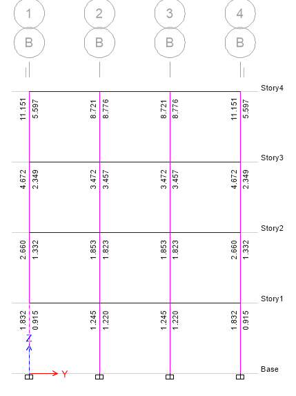
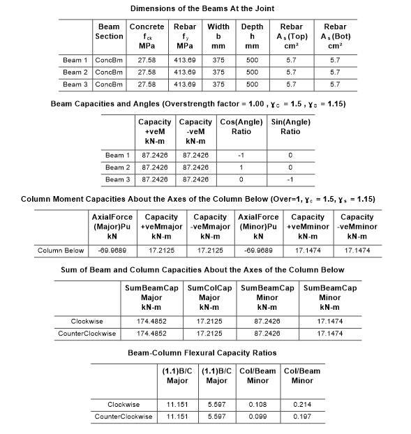
Hello to all, Here is something that's been troubling me lately: There is a huge variation in BCCR between lowermost and topmost floor. I have attached snaps with details also. I see that the Column capacity at top floor is very low as compared to lower ones. Why is there such variation? Am I interpretating the results the correct way???
- 6 replies
-
- b/c ratio
- beam column connection
-
(and 1 more)
Tagged with:
-
Dear all, can any one explain how Etabs calculate joint shear capacity of the RCC structure
-
when there is N/A in etabs column summary details what does it mean ? whether it is ok or revised the column and beam ? and when minor ratio is greater than 1 then what to do and what does it shows
- 1 reply
-
- beam column
- b/c ratio
-
(and 2 more)
Tagged with:
-
salam alekom many thanks to all engineers i got some questions about beam/column capacity ratio 1- how can modify SMRF in etabs for the frame? 2-what are the limit ration accepted for b/c capacity ratio ? thank
- 1 reply
-
- beam/column capacity
- b/c ratio
-
(and 1 more)
Tagged with:
-
Salaikom dear professionals, First of all I would like to express my sincere thanks to the initiators of this forum for establishing such an exceptional atmosphere for knowledge/experience sharing, I it is really useful, In fact since I have found the forum I am mostly online and busy reading the posts. I would also like to thank the members for their professional comments and advice. As my first post in this forum I would like to ask the following queries: 1-After running the analysis and design when I check the DESIGN DATA through Display >> Show Tables >> DESIGN DATA >> Concrete Frame Output, there is no specific message in Column Summary Data and Beam Summary Data, but in Joint summary data it is showing that “Joint B/C check not done”. Does anyone has any idea? I am sharing the ETABS model for your information and easy reference. ETABS MODEL.zip 2- ETABS provides greater area of steel in the upper column than the column at BASE, perhaps due to higher moment. Could someone explain why this is so? In practice should we maintain maximum steel in both stories? Or we shall follow what the software suggests? 3- Beside considering the minimum thickness required for deflection control of Beam as per Table 9.a Chapter 9 ACI-318 , using concrete crack behavior in ETABS and checking story drift, Do we have to check the deflection of beams for the serviceability propose elsewhere in ETBAS? If yes, Could anyone explain it? Regards, and look forward to any explanation
-
Assalam o alaikum.. My building is in zone 4 with SMRF. Majority of its column are Over stressed in 6/5 Beam Column Capacity Ratios. Columns are pass in all other checks. Size of column is 18x18 and building has just two stories. Longitudinal Reinforcement is ranging from 1% to 1.5%. Shear reinforcement going upto Av/s =0.18........ I cant increase size of column because it is already 18x18. How can i solve this problem??
- 1 reply
-
- (6/5) beam/column capacity
- beam/column capacity
- (and 2 more)






.thumb.jpg.700916fbc7ead330085e15745d0270bd.jpg)