Search the Community
Showing results for tags 'plate'.
-
I am trying modelling a simply supported plate model in with 10×10 mesh with density 25 Knm2 and E2510^6 and comparing it with results of other finite element applications and also with numerical matrix analysis by hand calculations. Both fem app and hand calculations results match but those of csi bridge and staad pro doesn't though they matched with each other. I was sure of correct modelling and also checked for equilibrium each time, I tried models of other dimensions l b and h as well. Each time fem results and hand calculations matched perfectly. For example I tried modeling 35×50 m plate with 2m depth. Hand and fem calculation results were 30 and 33 mm at centre resp. But csi bridge and staad pro for same parameters gives 230mm. For other models also the result are far too variable like this case only. Please I need urgent support. Any reference would be appreciated. Also how come two fem applications give these absurd results for exact same parameters?
-
Hello Everyone, Recently I have been busy with some checking work related to Shell structures in SAP2000 and Staad Pro. For plate analysis, I came across a good reference document. It is written for Staad but is very good for understanding of the plate forces and results as the plate force convention is almost same in all softwares (Designed for unit width, forces based on local coordinate system, and moment are in the direction of local axis). I can't remember where did I get this document as it was a direct download while exploring google. It is attached. Thank you. Plate Analysis Results and Design Forces in Computer Program.pdf
-
Hello everyone, need help regarding plate orientation issue in STAAD Pro software. I have model the structure in software and facing warnings in output file.
-
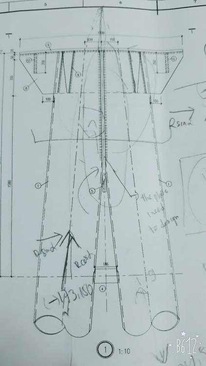
Assalamualaikum, Im designing a connection a pipe to pipe, between this pipe i have to add a plate to connect the pipe with welds. How can i determine the thickness of the pipe? Do i just design it based on tension load on the pipe? Cause my senior said that theres an eccentricity and i have to design it to resist such loads, but im not sure. Heres the figure of the drawing. Regards Groszni
- 1 reply
-
- plate
- connection
-
(and 2 more)
Tagged with:
-
Dear Engineers; Is it allowed to use the 2D-plate analysis for the raft?? Because the 2D neglects the inplane forced of the raft, Will it affect the out of plane forces?? if yes then I think it is not accurate for the analysis in presence of earthquake and wind loads coming from the superstructure, Am I right?? Or it just will neglect the results of analysis of in-plane forces without affecting the out of plane forces.? Regards
-
Hi, I am designing a load bearing masonry wall in ETABS and using IS 1905 code. After viewing the shell forces and stresses, I know that I need to use M11 forces for the design of lintel/horizontal bands to take out of plane lateral loading. But in ETABS i found that the forces are displayed in a unit of KN-m/m (per unit length). How do i convert this value to the total moment for the design of the band. Do I multiply this value by the shell meshing length? Please educate. Structural Engineer Nepal
-
Salam everyone, I have recently started using STAAD Pro for design of concrete. Need help with understanding how to read the plate stress contours to come up with design moment values. The values on the plate read for example 2500 lb-in/in. How do I interpret these results? Thanks
-
Respected engineers! in Etabs while defining slab it asks to select shell, plate and membrane. what is the diffrence between them and when and in which type of slabs we will use these?
-
Aslamualikum: I want to ask that, in ETABs, when we define slab, I put slab thickness same in MEMBRANE & BENDING, is it right or wrong? and what is difference b/w shell,membrane,plate and thick plate? and how and when we use these ? read out help topic in ETABs. But i could not understand.. Can anybody explain me in bit simplest way.?


