Search the Community
Showing results for tags 'seimic'.
-
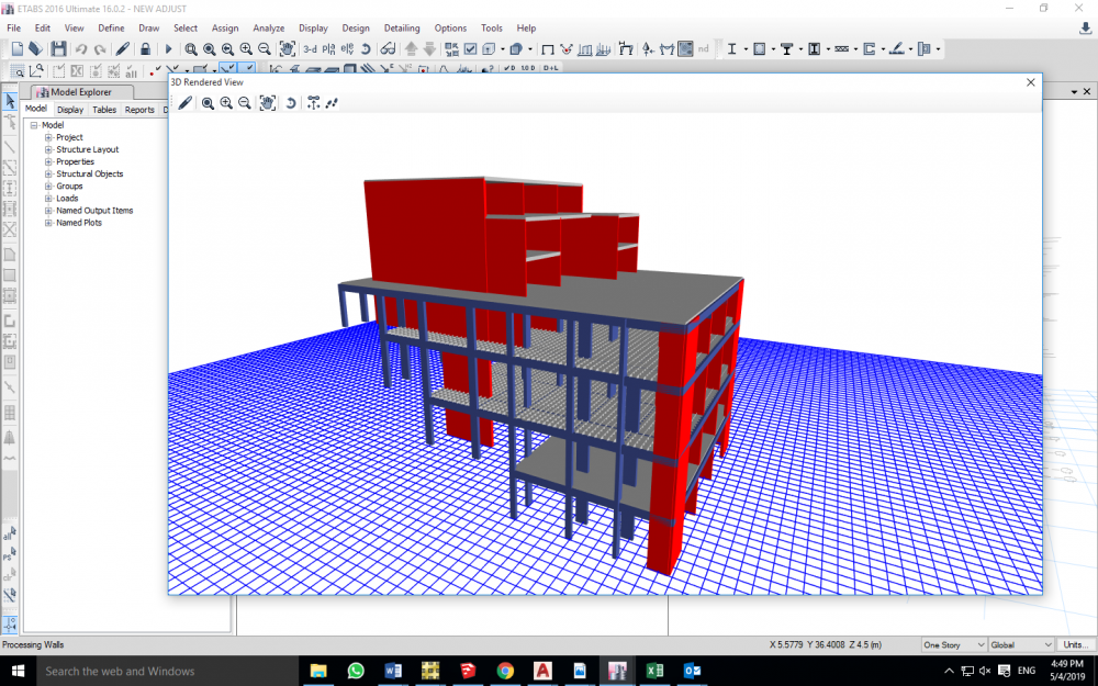
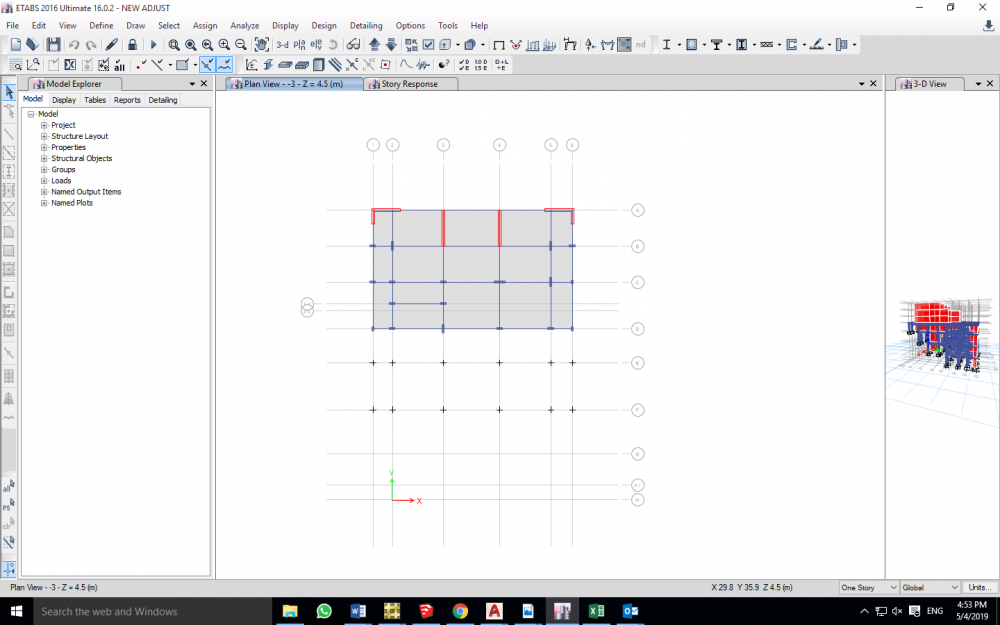
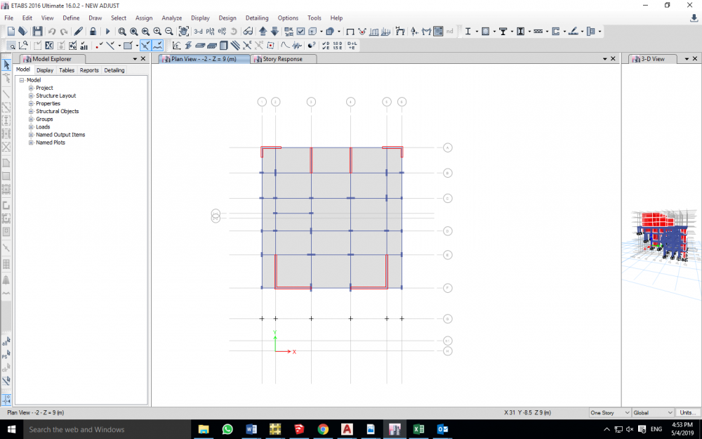
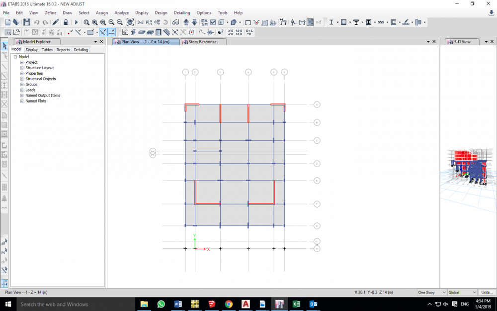
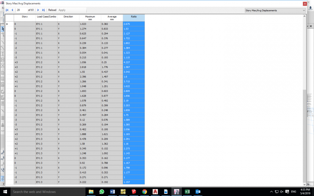
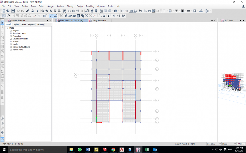
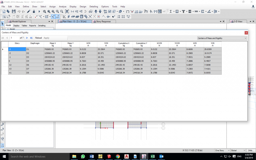
Hello Engineers So I'm having this 7 story building on a sloped land, the occupied levels will be from zero level (Street level) to +3 level , 4 residential stories. the bottom three -3,-2,-1 are being constructed on three levels in order to avoid drilling and any excavation work, considering that building is on hard rock (top of a mountain), and it will be very costly in order to do so. there are many problems that I have Encountered, and I truly need the help from you guys. -the first one is that the occupied stories's structural system is a load bearing walls, rested on Dual system of shear walls and moment resisting frames(the bottom three stories) and now I am Having soft stories , is it correct to model brick walls in the model, as they participate in their stiffness, and if modeled and still there is a soft story, what should I do? as you can see from the figures, the story geometry, specially -3,-2, is way less than that upper floors, and I can't go much deeper downwards in order to increase the number of vertical element. -in the 3 bottom levels+ zero level, Center of mass and center of rigidity are way far from each other, "way more than 5%L", which eventually causes Extreme torsional irregularity, More than 1.4 max drift to avg displacement values are obtained when checked to static load cases, I even Added the two shear walls at the top of the plan on order to pull center of rigidity closer to center of mass, But still, No point of that.I once heard from an Engineer, that Even if the building has torsional irregularity, when you design Piers and columns using Etabs, the program already takes care of that irregularity, as much as I want to believe that, But I think that torsional irregularity is a matter of a hole building geometry and behavior Plus it's a code requirement , and increasing the area of reinforcement won't help, what's right and what's wrong ?-is there any other checks that I should Do ? , is there any recommendations/Suggestions ? **I would truly Appreciate Your help. thank you.
-
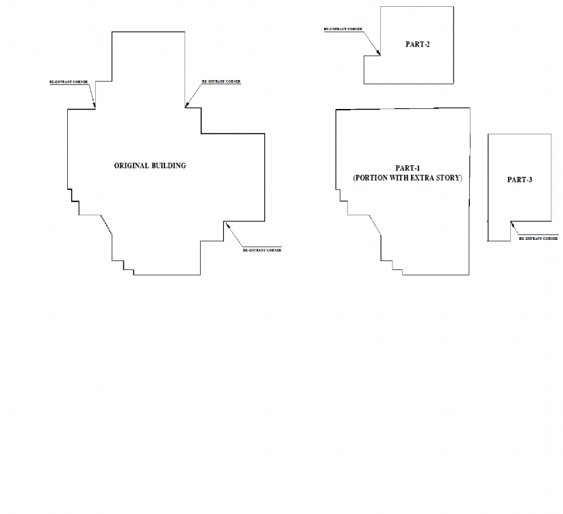
Assalam o alaikum. I am attaching image of plan of a building. It is having wing projections more than 15% as shown in attached image. And also Vertical irregularity i.e. Only center part of building has 3rd story and rest of parts dont have. I have the following questions. 1) To consider building a re-entrant corner or of irregularity type-2 according to UBS-Table 16-M, is it necessary for a building to have both side projects of a corner greater than 15% of dimension or even one side projection is greater than 15% still it will be considered as re-entrant corner? Table says for Re-entrant corners, refer 1633.2.9 item 6 and 7 which says, item 6 : "Connections of diaphragms to the vertical elements in structures in Seismic Zones 3 and 4, having a plan irregularity of Type 1, 2, 3 or 4 in Table 16-M, shall be designed without considering either the one-third increase or the duration of load increase considered in allowable stresses for elements resisting earthquake forces." Q: WHAT ABOUT STRENGTH DESIGN METHOD? WHAT IS ALTERNATE WAY OF CAPTURING THIS POINT IN STRENGTH DESIGN METHOD? item 7: "In structures in Seismic Zones 3 and 4 having a plan irregularity of Type 2 in Table 16-M, diaphragm chords and drag members shall be designed considering independent movement of the projecting wings of the structure. Q: WHAT IS A DIAPHRAGM CHORD AND DRAG MEMBER? WHAT THEY REPRESENT STRUCTURALLY IN A CONCRETE BUILDING? Each of these diaphragm elements shall be designed for the more severe of the following two assumptions: Motion of the projecting wings in the same direction. Motion of the projecting wings in opposing directions. Q : KINDLY EXPLAIN ITS WORDING? EXCEPTION: This requirement may be deemed satisfied if the procedures of Section 1631 in conjunction with a three-dimensional model have been used to determine the lateral seismic forces for design. 2) If i divide the building into 3 parts, still it have in Part 2 and 3 re-entrant corners. Should I consider It or as it seems not exceeding much than 15% in one direction, I can ignore it. It is basically a stair case. 3) The part 1 of building has an extra story i.e. total 3 stories but wings have only 2 stories. As it can be seen roughly from plan, The lower story is more than 130% of the upper story so It is, in my opinion, vertical geometric irregularity. Should I worry for this vertical geometry? Should I go for Dynamic anlysis as suggested by reference section for the same table to consider section 1629.8.4 item 2 which says "2. dynamic analysis shall be done for structures having a stiffness, weight or geometric vertical irregularity of Type 1, 2 or 3, as defined in Table 16-L, or structures having irregular features not described in Table 16-L or 16-M, except as permitted by Section 1630.4.2. " BUT AT THE SAME TIME section 1629.8.3 item 3 says " Static analysis is permitted for Irregular structures not more than five stories or 65 feet (19 812 mm) in height." and 1629.8.4 item 3 says "3. Dynamic analysis shall be done Structures over five stories or 65 feet (19 812 mm) in height in Seismic Zones 3 and 4 not having the same structural system throughout their height except as permitted by Section 1630.4.2." Hence Item 3 of both 1629.8.3 and 1629.8.4 says only if irregular structures are less than 5 story, static analysis is permitted but 1629.8.4 item 2 says for vertical irregularity dynamic analysis shall be done. Kindly explain. PS: I m planing to divide the building into 3 parts and shown to avoid any of the irregularity. But if in certain case, i can not divide it, how to interpret the UBC conditions. Thanks.
- 6 replies
-
- re entrant corner
- vertical irregularity
-
(and 2 more)
Tagged with:
.thumb.jpg.700916fbc7ead330085e15745d0270bd.jpg)
