Search the Community
Showing results for tags 'steel' or 'bridge'.
-
Looking for worked examples on Highway and Railway Bridge Design in compliance with Eurocode. Appreciated!
-
Concrete box culvert design on CSI bridge, if we restrained bottom by fixed support than answer of moments and shear are coming less???? And shear and moments should come more on bottom slab than top???? Plz guide
-
Anyone can guide me through the Code & Standards that are required for Design of Bridges?
- 1 reply
-
- bridge
- structural design
-
(and 1 more)
Tagged with:
-
how to calculate the amount of steel used in your designs, for example, your latest housing building, commercial buildings, warehouses, etc., in terms of weight of the structure per area of it. Some of my clients tell me that I use too much steel, and that they have "other" engineers that will provide lighter structures. Are there really rules of thumbs for this?
-
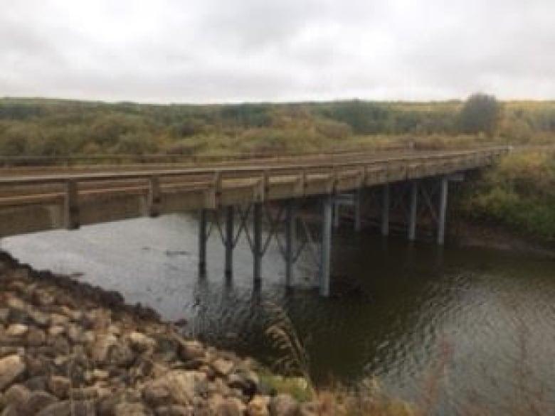
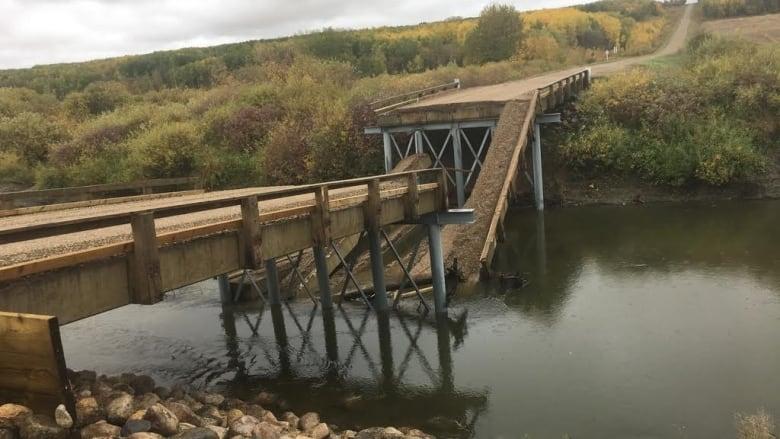
Bridge that collapsed six hours after opening was built without geotech investigation of riverbed: Reeve Read more: https://www.cbc.ca/news/canada/saskatchewan/bridge-that-collapsed-six-hours-after-opening-was-built-without-geotech-investigation-of-riverbed-reeve-1.4829890
-
How did the structure collapse? It fell around 11:30 local time (09:30 GMT) during heavy rain. Police reported a violent cloudburst. "It was just after 11:30 when we saw lightning strike the bridge," eyewitness Pietro M all'Asa was quoted as saying by Italy's Ansa news agency. "And we saw the bridge going down." Another witness, unnamed, recalled: "We heard an incredible roar and first we thought it was thunder very close by. "We live about 5km [three miles] from the bridge but we heard a crazy bang... We were very scared... Traffic went completely haywire and the city was paralysed." Read more: https://www.bbc.com/news/world-europe-45183624 Lets see what the root cause analysis determines the cause of failure. Feel free to share your thoughts.
-
AoA, If somebody could refer me to any specific design guides tailored for PEB structures specifically would be of great help, thanks!
-
Working on a steel structure, I used LRFD as well as ASD. The fact that some components of the structure fail in ASD while in LRFD they pass with nearly minimum stress ratios, has left me in an awe. Kindly put in your reviews to which methodology should be adopted and what might be the flaws in using ASD or LRFD concerning Steel Structures. Thanks.
-
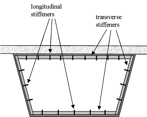
Salam everyone, I doing some research on stiffened box girder bridges but I'm having some trouble finding the right one. If anyone has access to some papers or textbook examples or a bridge they designed it would really help me out. Specifically I'm looking for a steel box girder bridge (trapezoidal or rectangular) that has its flanges and/or webs stiffened with welded longitudinal stiffeners. More than one stiffener is preferred (refer to attached image). I need the cross-sectional dimensions and stiffener dimensions too if possible. I have attached a few images as reference. Thank you for your time and help in advance.
- 2 replies
-
- bridge
- stiffeneres
-
(and 1 more)
Tagged with:
-
Read more: https://www.cbsnews.com/news/florida-bridge-collapse-fiu-florida-state-university-project-behind-schedule-over-budget-updates-2018-03-20/
-
Assalamualaikum, im designing beam to column connection, i wanted to know what are some limit states on the beam and also on the column? and also i need a correction in my design, heres what i did : 1. designed the top and down flange groove weld to resist tension caused by Mu, Tu=Mu/(h-1/2tf.2) 2. designed amount of bolts on the web based on shear force 3. designed the connection plate on the web based on the shear force / axial (tension force) on the beam. 4. designed the fillet weld based on shear force acting on the beam what else i have to check/design? thank you regards.
- 7 replies
-
- steel
- connection
-
(and 1 more)
Tagged with:
-
Salam everyone. I'm doing a study for fatigue crack growth in a steel box girder bridge. For that I need the loading history (or strain history). If anyone can share it, it would be greatly appreciated. Regards, Haider Ali
-
Greetings All, Technopole industries is a UAE based pole manufacturing factory which is currently in a requirement for a hard working, let me repeat that again an extremely hard working structural engineering to be part of our team. The Factory manufactures Steel poles & Mast more information can be found on Technopole Industries website. interested candidates can inbox me or drop their CV at fawad@technopoleindustries.com. Best Of Luck Guys
-
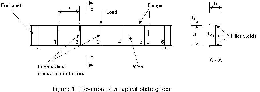
Assalamualaikum, im designing a steel beam. The nominal shear is already meets the requirement which is larger than the required shear force (Vi*Vn > Vu). But my senior engineer said that i have to design an additional stiffener to resist the force when it comes to erection later. How do i design this transverse stiffener considering there nomore shear to resist? is there any provision on AISC about minimum spacing and the thickness of plate required? thanks
-
Dear All, Can any one tell me how to model surge girder of 18 m span in sap or any other relevant software.
-
Dear All, I have designed the bridge between two building. Fixed at one end and roller at the other. The bridge at the roller end, rests on a concrete ledge. I have provided the expansion joint based on the formulation of ASCE for building separation. I have certain queries on it : 1- Is building separation formulation is appropriate to provide expansion/moment joint in my case? 2- I am trying to allow the movement through slotted holes in base plate. If my bridge required expansion is 300mm through formulation indicated in Point-1 above, should the slotted hole be twice of it i.e. 2x300mm = 600mm I am still unsure as to what size the slotted hole should be ? and what governs the expansion joint of bridge over the ledge end. I am relatively new to bridges. any help would be highly appreciated. Thanks in advance.
- 9 replies
-
- expansion
- slotted hole
-
(and 1 more)
Tagged with:
-
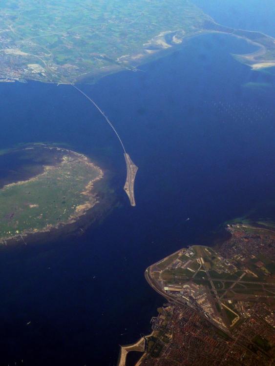
Assalam-o-alaikum, Dear Colleagues! The Øresund bridge is an engineering marvel that connects the Danish capital of Copenhagen to the Swedish city of Malmö. A cable-stayed bridge runs nearly 8 km (5 miles) to an artificial island where it transitions into a tunnel that runs another 4 km (2.5 miles). The award-winning double-track railway and motorway opened on July 1, 2000. For more details refer to the following link: http://twistedsifter.com/2015/09/oresund-bridge-turns-into-tunnel-and-connects-denmark-and-sweden/
-
Salam Girders of a bridge during launching collapsed. it is reported it happened due to heavy winds during launching of the girders,links for further details are attached. http://tribune.com.pk/story/1109218/rs330m-jhelum-bridge-collapses-ahead-inauguration/ http://www.baaghi.tv/330-million-jhelum-bridge-collapsed-due-to-substandard-material-and-negligence-of-highways-department/ Regards
- 2 replies
-
- mishap
- girder launching
-
(and 2 more)
Tagged with:
-
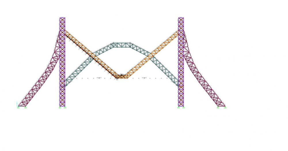
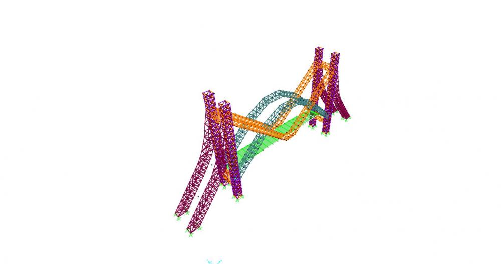
SALAM I have been working on a pedestrian bridge design steel structure, i have attached two snaps from sap2000 for the concept. All four towers and arches will have cladding in round shape. I have assumed bolted connections. if i assign moment release to both ends of the members i get my sections passed within .70-.80 dc ratio but when there are no moment releases assigned dc ration reaches 3.5. Pu abruptly decreases in case of moment releases. i described the member results for the lowest members of the main tower.results comparison attached excel sheet. some valuable input is requested. Regards result comparison.xlsx
-
Can some body please give reference regarding torsional design of post-tensioned bridge girders? I have searched through AASHTO LRFD Bridge Design Specs but could not find a valid reference.
-
- prestressed
- torsion
-
(and 5 more)
Tagged with:
-
Hi guys In the question i have a super T girder with some reinforcement. Ques is I have to calculate compression strength in concrete block using formula C = gamma * 0.85 f'c * b (width) what value of b should i use to calculate this compressive force? thanks Saad
-
Assalamualaikum dear forum members, I am currently designing a 35m span prestressed precast I beam bridge. The deck is formed from 300 rc insitu slab and the beams are 1.8m deep precast I beams. These span simply supported onto bearings shelf/abutment. Due to a high watertable, a secant pile wall option is used to form the abutments (with a hard/soft pile configuration). There is also a raft to form the underpass and act as a prop to the secant walls. The secant walls are formed from 1200mm diam. piles and the raft is currently 2m deep. Apparently another engineer (quite senior) advised to have the raft dowelled into the piles, i.e. maybe 3 dowels per pile in the secant and then continued into the raft at an appropriate anchorage. The 35m span deck is supporting a curved road on top and the underpass is supporting 6 lanes of traffic. The whole bridge is designed to AASHTO I have a few issues which are troubling me which I would like to ask for opinions on; 1) The prestressed I beams at ULS are sagging as they are simply supported. At SLS the ends are hogging; is this due to the prestressing force being too much? The secant pile wall is being designed by geotech. I assume that under any limit states as the deck is supported on bearings, the forces transferred to the secant will only ever be axial forces and shears ie. fx, fy, fz? 2) The raft/ secant pile wall connection does not sound particularly convincing to me. The actual secant pile wall is very long and is about 480m. The raft slab therefore has movement joints every 10m or so. I thought that the raft plus secant could either be considered as an inverted portal frame or as a wall with a lateral prop. The senior engineer want to assume this is acting as an inverted portal frame but how can we have fully fixed moment connection with 3 dowel bars! Also if the abutment was actual wall, the raft could be detailed with rebar to be cast as a full moment connection, but with the secant the rebar will be very congested and I do not know an easier way to achieve this full moment connection of the raft with the secant. Please advise.
-
Hello Everyone, I have a Steel Hangar Structure to design at my office and I've been trying to do that using ETABS. The dimensions of the structure are 130'x95' and maximum bay spacing is 24'-5". Clear Height is 33' from NSL and thee apex is at 38' from NSL. Seismic zone is 2B and Wind Category is C. The issue I am having is that ETABS is failing the members despite many tries and framing adopted. I also tried doing it in 2D using SAP but still the members were failing. Columns due to kL/r being more than 200.(manual calculations showed that kL/r < 200) and purlins because of torsion. Kindly suggest what to do? and If some has any manual calculations or some literature to study for this problem. Rana Waseem Bhai and Umar Makhzumi Bhai! I am attaching the .edb and .ebk files of the model. V1.0.$ET V1.0.EDB
-
Has anyone done the wind analysis on bridges using British Standards ( BD 37/01). I have a few questions regarding its application on structure and live load both.


